Singapore lifted its three-year moratorium on new data centre approvals in 2022, and the pipeline has moved quickly since. Four operators — AirTrunk-ByteDance, Equinix, GDS, and Microsoft — were awarded a combined 80 MW under the first Data Centre Call for Application (DC-CFA1) in 2023. A second call for at least 200 MW closed applications in March 2026. In October 2025, the Economic Development Board and JTC announced up to 700 MW of low-carbon capacity earmarked for a dedicated park on Jurong Island. None of that capacity runs without a plant room, and every plant room comes with a chilled-water and condenser-water piping network sized to reject heat around the clock for the life of the building.
For the engineers and M&E contractors specifying that piping, the headline megawatt figures matter less than a narrower, practical question: which sections of the loop take a mechanical coupling, which take a weld, and which are governed by a fire code that rules out mechanical joints altogether. This guide covers the topology of a typical Singapore data centre cooling loop, the pipe sizes and codes that apply to it, and where mechanical couplings fit — and where they do not.
Singapore’s Data Centre Build Wave
Singapore’s total installed IT-load capacity is approximately 1.4 GW across more than 70 data centres, with market vacancy around 1.4% — the tightest in the Asia-Pacific region. Every additional approved megawatt is effectively a guaranteed construction event. The construction market itself reflects that: Singapore’s data centre construction spend was estimated at USD 4.56 billion in 2025, forecast to grow to USD 6.01 billion by 2031.
| Milestone | Detail |
|---|---|
| DC-CFA1 (2023) | 80 MW awarded to four operators: AirTrunk-ByteDance, Equinix, GDS, Microsoft |
| DC-CFA2 (2025–26) | Minimum 200 MW; applications closed March 2026; requires PUE ≤ 1.25, BCA-IMDA Green Mark Platinum, ≥50% green energy sourcing, and equipment exceeding SS 715:2025 |
| Jurong Island DC park | Up to 700 MW on ~20 hectares, announced October 2025; supported by ~300 hectares reserved for hydrogen, ammonia, and battery-storage infrastructure |
| Construction spend | USD 4.56B (2025) rising to USD 6.01B by 2031, at a 4.70% CAGR |
A useful rule of thumb for scoping the mechanical plant behind any of these projects: each 1 MW of IT load typically requires roughly 1.5 to 2.5 MW of total MEP plant capacity, once cooling, power distribution, and redundancy are accounted for.
The Cooling Loop: Chilled Water and Condenser Water
A typical Singapore data centre cooling system runs two linked water circuits. Chilled water (CHW) is supplied to the CRAH units, rear-door heat exchangers, or cooling distribution units serving the server racks, typically at a supply temperature in the 6–14°C range with a return around 12–21°C, depending on the specific cooling strategy the facility uses. That heat is rejected at the chillers — centrifugal, absorption, or magnetic-bearing units — into a separate condenser-water (CDW) loop, typically running at a supply of around 30°C and a return around 35°C, which discharges to cooling towers, dry coolers, or, at coastal or island sites, seawater heat exchangers.
Where a facility sits on or near the coast — including the planned Jurong Island low-carbon park — seawater intake and discharge piping becomes part of the heat-rejection path alongside or instead of cooling towers, running at considerably larger bore than the plant-room headers.
Pipe Sizes and the Applicable Codes
Pipe sizing in a Singapore data centre plant room scales with the size of the facility, but typical ranges are consistent across projects:
| System | Typical size range |
|---|---|
| CHW mains (plant room) | DN100–DN600, PN10–PN16 |
| CDW mains (plant room) | DN150–DN800, PN10–PN16 |
| Cooling-tower risers | DN200–DN600 |
| Seawater intake/discharge (coastal, Jurong Island) | DN300–DN1200 |
| Pre-action sprinkler mains | DN50–DN300 |
| Clean-agent suppression (FM-200/Novec/IG-55) | DN25–DN200, typically schedule 40 or 80 steel |
The code that governs a given section of pipe depends on what it carries. CHW and CDW plant-room piping falls under ASME B31.9 (Building Services Piping), with SS 553:2016+A1:2017 applying on the ACMV building-services side. Some consultants specify large CHW/CDW mains to BS EN 806 or CIBSE guidance instead of B31.9, largely as a matter of house preference. Pre-action sprinkler systems fall under NFPA 13 together with SS 544 and SCDF requirements. Clean-agent suppression systems follow NFPA 2001 and the relevant local Authority Having Jurisdiction. Seawater intake and discharge piping is classified under either ASME B31.3 or B31.9 depending on service classification.
Where Mechanical Couplings Fit in the Plant Room
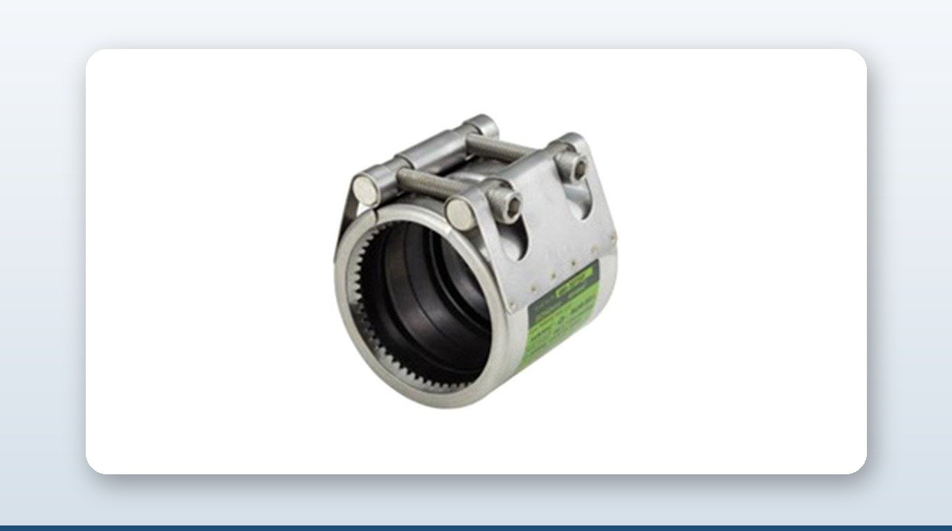
Buried CHW and CDW trench mains are typically welded or flanged steel, and mechanical couplings play a limited role there. Inside the plant room and at the equipment boundary, the picture is different. Chiller and cooling-tower pump suction and discharge connections are a standard application for flexible mechanical couplings, which accommodate the vibration generated by rotating equipment and give the pipe some tolerance for minor misalignment at the pump base. Header tie-ins and riser connections — where the pipe run needs a controlled degree of axial restraint rather than a rigid flanged joint — are typically served by grip-type mechanical couplings on plain-end pipe.
Scale matters here. A single chiller can require anywhere from 50 to 2,000 refrigeration tons of capacity, and a 20 MW data centre plant room can house 10 to 40 chiller units. Each chiller typically needs four to eight coupling connections at minimum across pump suction, discharge, and header tie-in points — which means a 100 MW facility’s plant room alone can involve several hundred to over a thousand individual coupling connections.
Cooling-tower risers present a related but distinct problem: CDW piping running from a basement plant room up to rooftop cooling towers can span 10 to 25 storeys, and that run needs to accommodate significant thermal expansion and vibration over its height. Expansion joints handle the thermal growth on these long vertical runs, typically paired with flexible couplings at each riser tie-in point.
The Fire-Protection Exception
Pre-action sprinkler risers and headers are a distinct product category from the mechanical couplings used on CHW and CDW plant-room piping, and the distinction matters. NFPA 13 and SCDF requirements mandate that grooved couplings used on fire-protection systems carry UL listing or FM approval specific to that service. A grip-ring coupling designed for plain-end pipe — the type used on CHW/CDW header tie-ins — is a different joint geometry from a grooved-end coupling and is not, on its own, a substitute for an FM- or UL-listed grooved-end fire-protection product. Specifying engineers should treat pre-action sprinkler and clean-agent suppression piping as a separately certified scope, sourced from suppliers carrying the specific fire-protection listing, rather than assuming standard mechanical-coupling ranges extend to fire main.
Ageing Plant and In-Service Repair
Singapore’s data centre stock is no longer uniformly new. The earliest facilities in the current cluster date to 2005–2015, and some CHW and CDW piping is now approaching or past 20 years in service. That creates a practical constraint: draining a live chilled-water loop on a Tier III or Tier IV facility to reweld a leaking section risks a service interruption that most operators will not accept. Mechanical repair clamps, applied without draining the system, are the standard answer to in-service leak patching on legacy CHW and CDW headers in this scenario — a maintenance-side application that is separate from, but just as real as, the new-build coupling scope described above.
Key Takeaways
- – Singapore’s data centre construction pipeline is active and accelerating, with DC-CFA1, DC-CFA2, and the 700 MW Jurong Island park all generating plant-room piping demand through 2031.
- – Chilled-water and condenser-water loops are the mechanical-coupling scope in a data centre; buried trench mains are typically welded, while plant-room and riser connections are standard flexible or grip-type coupling territory.
- – Pipe sizing scales from DN100 up to DN1200 at the seawater end, governed primarily by ASME B31.9 and SS 553:2016+A1:2017 for CHW/CDW plant-room piping.
- – Pre-action sprinkler and clean-agent suppression systems require UL- or FM-listed grooved-end couplings under NFPA 13 and SCDF requirements — a distinct, separately certified scope from standard mechanical couplings.
- – As the data centre estate ages, in-service repair clamps are becoming a practical necessity for maintaining CHW/CDW headers without the service interruption a full drain-down would cause.
About David Phee Enterprise
David Phee Enterprise supplies mechanical pipe couplings, expansion joints, and repair clamps to industrial and infrastructure projects across Singapore, Malaysia, and Indonesia from its Kaki Bukit headquarters, with same-day delivery across the region. As the exclusive Singapore distributor for JWC (Jeong Woo Coupling), DPE supports plant-room piping specifications for data centre chilled-water and condenser-water systems. For technical enquiries, visit davidphee.com or get in touch directly.