Cargo piping is the most heavily-welded system on a tanker, and that is by design. Whether the parcel is crude oil, methanol, liquefied propane, or LNG at -163°C, the rulebook governing tanker cargo piping coupling selection is written to squeeze mechanical joints out of the primary containment path wherever possible. For chemical, LNG and LPG carriers specifically, the IMO’s IBC and IGC Codes go further than a general “welded preferred” guideline — they specify exactly which joint types are permitted, at what diameter, and under what temperature.
This article works through the joint rules and material selection for each of the four tanker cargo types — oil, chemical, LPG and LNG — and identifies the narrow set of cargo-adjacent lines where mechanical couplings remain a legitimate, class-approved choice.
Four Cargo Types, Four Different Envelopes
Cargo piping on a tanker is regulated by which product sits in the tank, not by which class society writes the rules. The governing code, temperature envelope and default material vary sharply across the four vessel types:
| Vessel type | Governing IMO code | Cargo envelope | Material default | Welded vs mechanical |
|---|---|---|---|---|
| Crude / product oil tanker | MARPOL Annex I + class rules (no IMO joints code) | Ambient (10–45°C), max ~80°C for HFO trace-heated | Carbon steel ASTM A106 Gr.B Sch.40, internally epoxy-coated for product | Welded ≥95% by practice; mechanical permitted but rare on cargo main |
| Chemical (IMO Type 1/2/3) | IBC Code (MSC.4(48), Ch.5) | −50°C to +180°C parcel-by-parcel | 316L stainless default; duplex 2205 for acids; epoxy/phenolic linings on CS for some parcels | “All joints except valves or expansion pieces must be welded” (IBC §5.3) |
| LPG (semi-pressurised / fully refrigerated) | IGC Code (MSC.5(48), Ch.5) | −50°C (refrigerated) to +45°C (pressurised); design pressure 5–18 bar | C-Mn notch-tough steel to −55°C; 304L for colder ethylene/propylene service | Per IGC §5.8: butt-weld preferred; mechanical only on instrument/open-ended lines ≤25–50 mm |
| LNG carrier (membrane/Moss) | IGC Code (MSC.5(48), Ch.5) | −163°C atmospheric in tank; cargo main at saturation pressure | 304L / 316L cryogenic stainless for piping; Invar 36 for membrane primary barrier only | Per IGC §5.8: butt-weld only on cargo main; slip joints prohibited outside cargo tank (§5.8.4) |
Oil Tankers — Industry Practice, Not IMO Code
Oil tanker cargo piping is the simplest of the four. Cargoes — crude, gasoline, gasoil, diesel, jet, lube base oils, residual fuel oils — sit at ambient temperature or are trace-heated to 60–80°C for HFO and asphalt-precursor parcels. Design pressure on the cargo main is set by the cargo pump deadhead, typically 8–12 barg on the discharge main and 2–4 barg on the loading main.
The standard material is ASTM A106 Grade B seamless carbon steel, Schedule 40, to ANSI B36.10 dimensions. Product carriers running clean white oils, MGO or jet fuel often specify an epoxy- or phenolic-coated internal surface to stop rust pickup contaminating the cargo. The joint mix on a typical VLCC or Suezmax cargo main runs: welded butt joints on the main, all branch tees and bellmouths; bolted flanges at every cargo valve, pump suction/discharge and manifold connection; expansion bellows at engine-room boundary penetrations and pump discharge points; and mechanical couplings only on slop tank lines, the tank-cleaning ring main, the MARPOL stripping line, and drip-tray drains under the manifold.
There is no IMO code prohibition on mechanical couplings for oil tanker cargo piping — the constraint is class rules (DNV Pt.5 Ch.5, ABS Steel Vessel Rules Part 5C, LR Pt.5 Ch.12) plus the OCIMF “Recommendations for Oil and Chemical Tanker Manifolds,” which specifies flanged ANSI 150 (or 300 for high pressure) carbon-steel connections at the ship/shore interface, with insulating flanges to break the static-electricity path. No mechanical couplings sit at the manifold face itself.
Chemical Tankers — IBC Code Joint Rules
Chemical tankers are the cargo-piping challenge case. A modern IMO Type 2 chemical tanker may carry 30–50 different parcels in a single voyage, each in a dedicated tank with its own cargo line, pump and manifold connection — the segregated system that drives material selection down to the individual parcel:
| Parcel | Temperature | Material |
|---|---|---|
| Ambient parcels (methanol, MEG, acetone, palm oil) | 5–40°C | 316L stainless |
| Refrigerated parcels (some halogens, butadiene at −5°C) | down to −50°C | 304L / 9% Ni |
| Acid parcels (sulphuric 98%, phosphoric 75%, hydrochloric) | ambient but corrosive | Duplex 2205 (sulphuric), super-duplex (HCl), 316L epoxy-lined CS (less aggressive acids) |
| Caustic parcels (NaOH 50%, KOH) | ambient–80°C | 316L (cold) → Inconel 625 cladding (hot caustic) |
| Heated parcels (asphalt 180°C, molten sulphur 140°C, phenol 80°C) | 80–250°C | Steam-jacketed CS or 316L; trace-heated lines |
IBC Code §5.3 is unambiguous on joints: “All joints in cargo piping, except those to valves or expansion pieces, must be welded.” In practice this means butt-welded main lines and branches, flanged connections only at valves, pumps, manifolds and expansion pieces, slip-on welded joints permitted only ≤50 mm OD on open-ended or instrument lines, and screwed/threaded joints permitted only ≤25 mm OD on accessory lines. Mechanical couplings — slip-on, grooved, or grip-type — are not permitted on primary cargo containment; class will reject a grip-type coupling on the cargo main itself. The manifold ship/shore interface is stainless-steel flanged, typically 316L for chemical service.
LPG Carriers — Three Pressure Classes
LPG carriers come in three configurations, each with its own pressure and temperature envelope:
- – Fully pressurised — small vessels up to roughly 3,000 m³, spherical or cylindrical Type C tanks, design pressure around 18 bar, cargo at ambient temperature (−5°C to +45°C). Material: C-Mn steel. No insulation, no reliquefaction.
- – Semi-pressurised / semi-refrigerated — 3,000–25,000 m³, Type C cylindrical tanks, design pressure 5–7 bar, cargo at −10°C to −48°C. Material: low-temperature C-Mn steel or 3.5% Ni steel to −55°C, with reliquefaction on board.
- – Fully refrigerated — 25,000–85,000 m³ VLGCs, Type A prismatic tanks with full secondary barrier, design pressure around 0.25 bar, cargo at −48°C (propane) or −104°C (ethylene). Material: low-temperature C-Mn steel for propane/butane; 9% Ni steel or 304L for ethylene.
IGC §5.8 joint rules apply identically across all three classes. The one place mechanical joints genuinely win on an LPG carrier is the deck cargo main between tanks, which runs 80–120 metres fore-aft. Thermal cycling from around +30°C ambient (a ship sitting hot in Singapore Roads) down to −48°C cargo flow during loading or discharge produces roughly 20 mm of axial thermal growth per 10 metres of pipe. This is absorbed by multi-ply stainless or Inconel bellows welded into both ends of the line — IGC §5.8.4 explicitly permits expansion bellows while prohibiting slip joints. Manifold flexibles on LPG carriers use rigid hard arms or composite cryogenic hoses at the ship/shore connection, not metal mechanical couplings.
LNG Carriers — The Strictest Regime
LNG carriers hold the tightest joint rules of any cargo type. Cargo sits at −163°C atmospheric pressure inside the containment system, with the cargo main running at saturation pressure of roughly 1.06 bar absolute. The material set reflects the cryogenic extreme:
| Component | Material | Reason |
|---|---|---|
| Membrane primary barrier (Mark III / NO96) | Invar 36 (Fe-36%Ni) | Coefficient of thermal expansion 1.2×10⁻⁶/°C — near-zero — so the 0.7 mm membrane doesn’t tear at −163°C |
| Moss spherical tank | 9% Ni steel or 5083 aluminium | Notch toughness retained at −163°C |
| Cargo piping (deck main, vapour main, loading/discharge headers) | 304L or 316L austenitic stainless | Austenite crystal structure resists brittle fracture at cryogenic temperature |
| Cargo pump tower, columns, hardware | Inconel 625/718 (selective use) | High strength plus cryogenic toughness and low thermal contraction |
IGC §5.8 is enforced strictly on the cargo main: butt-welded full-penetration joints, double-welded for service below −10°C (§5.8.2); welded-neck flanges only below −55°C, with slip-on flanges prohibited (§5.8.3); and slip joints prohibited outright anywhere outside the cargo tank (§5.8.4) — there is no compression coupling or grip-type mechanical coupling anywhere on the LNG cargo main. Expansion bellows are permitted with anti-icing protection. The full restriction table:
| IGC §5.8 sub-section | Joint type | Permitted? |
|---|---|---|
| §5.8.2 — Butt-welded | All cargo / process piping | Yes (with §5.9 NDE) |
| §5.8.2 — Slip-on welded | Open-ended / instrument lines, ≤50 mm OD, ≥−55°C | Yes |
| §5.8.2 — Screwed couplings | Accessory / instrument lines, ≤25 mm OD | Yes |
| §5.8.3 — Welded-neck flange | All applications | Yes |
| §5.8.3 — Slip-on flange | Above −55°C, ≤100 mm nominal | Yes (limited) |
| §5.8.4 — Slip joints | Anywhere outside cargo tank | No — prohibited |
| §5.8.4 — Expansion bellows | Anywhere (with anti-icing) | Yes |
Where mechanical joints do survive on an LNG carrier: the cargo manifold ship/shore connection uses ANSI B16.5 weld-neck flanged bolted connections plus an emergency release coupling on the loading-arm side; the vapour return manifold is likewise flanged bolted; and N2 inerting, purge, sampling and instrument lines carry small-bore (≤25 mm) screwed couplings under §5.8.2.
Where Mechanical Couplings Actually Fit
Despite the welded bias across all four cargo types, mechanical couplings do appear on cargo-related piping in specific, auxiliary locations:
- – Cargo manifold drip-tray drains — small-bore (DN50–DN100), often retrofit, low-pressure, gravity-drained. Class accepts type-approved mechanical couplings here.
- – Tank-cleaning ring main / Butterworth lines — warm seawater service, Class II/III piping rather than cargo containment.
- – Slop tank piping — small-bore stripping line, low pressure, ambient temperature.
- – COW (crude oil washing) lines downstream of the COW machine — welded primary, with mechanical couplings acceptable at maintenance access points only.
- – Cofferdam vents, instrument lines and gauging lines — small-bore ≤25 mm, screwed couplings explicitly permitted under IGC/IBC §5.8.2.
- – Vapour return lines on chemical/LPG carriers (not LNG) — flanged bolted, with some societies accepting type-approved grip couplings on ambient sections.
- – Emergency repair clamps over a pinhole or crack on a cargo line — a non-permanent fix pending the next dry-dock weld repair, accepted by class as a temporary measure logged as a survey defect.
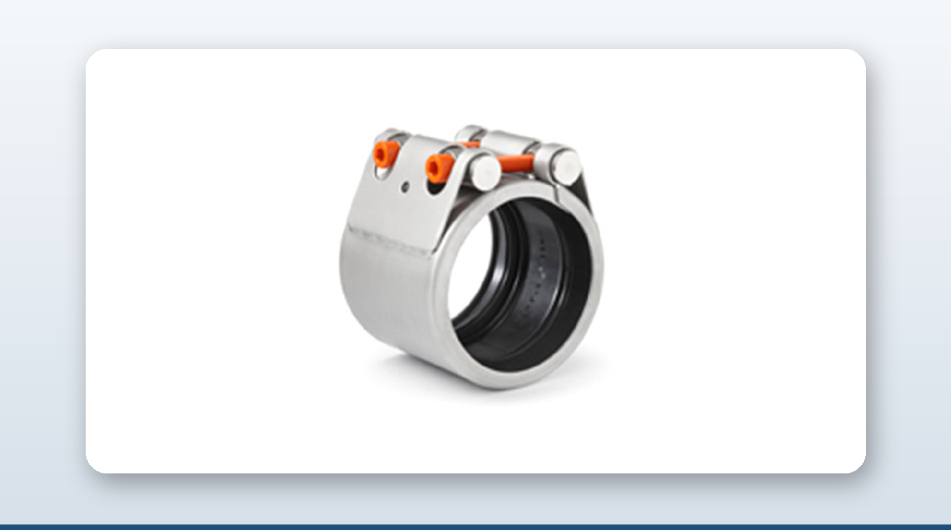
JWC MJS and MJG flexible couplings, DN50–DN600, are the practical fit for the manifold drip-tray drains, tank-cleaning ring main, slop-tank piping and COW maintenance access points, with Korean Register type approval being the easiest first certification for a Korean-built tanker. JWC MJG with Fire-Resistant Cover addresses ISO 19921/19922 fire endurance requirements on warm cargo-adjacent lines. A-Ju multi-ply stainless, 316L or Inconel bellows are the direct answer to the thermal-growth problem on LPG and LNG deck cargo mains, and stainless bellows with steam-jacketed casing serve chemical heated cargo lines. Romacon repair clamps hold working pressures up to roughly 10 bar — covering all chemical/oil cargo mains and LPG fully-refrigerated suction lines at 5 bar — but standard Romacon EPDM/NBR gaskets are not cryogenic-rated, so LNG cargo lines need a cryogenic-rated repair sleeve instead.
The rule that matters most for anyone specifying on the cargo main: never sell a mechanical coupling as primary containment on a chemical, LNG or LPG carrier. It will fail survey under ABS, DNV or KR class rules the moment a surveyor checks the joint against the IBC or IGC Code.
Key Takeaways
- – IGC §5.8 permits butt welds everywhere on the cargo main but restricts slip-on welded joints to ≤50 mm OD on open-ended/instrument lines above −55°C, screwed couplings to ≤25 mm OD instrument lines, and prohibits slip joints outright anywhere outside the cargo tank.
- – IBC §5.3 requires all chemical tanker cargo piping joints to be welded except those at valves or expansion pieces.
- – LNG cargo sits at −163°C atmospheric and uses 304L/316L austenitic stainless for the cargo main, with Invar 36 reserved for the membrane primary barrier only.
- – LPG spans a −48°C (fully refrigerated propane) to +45°C (fully pressurised) envelope across three distinct carrier configurations, each with its own design pressure and material default.
- – Oil tanker cargo mains run ASTM A106 Grade B Schedule 40 carbon steel and are welded in ≥95% of joints by class-rule practice, even though no IMO code specifically mandates it.
- – Mechanical couplings fit only the auxiliary cargo-adjacent lines — manifold drip-tray drains, tank-cleaning ring mains, slop-tank stripping lines and small-bore instrument connections — never the primary cargo main on chemical, LNG or LPG carriers.
About David Phee Enterprise
David Phee Enterprise is the exclusive Singapore distributor for JWC pipe couplings, stocked at Empire Technocentre, Kaki Bukit for same-day delivery, alongside A-Ju metal-bellows expansion joints for LPG and LNG deck cargo main thermal growth and Romacon repair clamps for emergency, non-permanent containment of a cargo-line defect pending dry-dock weld repair. The cargo main itself is welded by IMO code on chemical, LPG and LNG carriers, so DPE’s coupling business sits around it — manifold drip-tray drains, tank-cleaning ring mains and slop-tank stripping lines — not on the primary joint. For coupling specs or certification documentation on any of these ranges, contact DPE or browse the full catalogue at davidphee.com. Related reading: marine piping Class I, II and III explained and mechanical coupling vs flange.