The question of mechanical coupling vs flange high pressure performance is not simply resolved by picking one or the other. Both joint types are proven across industrial and marine applications — the decision turns on working pressure, site constraints, maintenance access, and lifecycle cost. Engineers who default to flanges out of convention may be over-engineering joints in moderate-pressure systems; those who reach for mechanical couplings on every application risk under-specifying at genuinely high-pressure nodes. This guide compares both joints on the criteria that matter: how each works, pressure capability, installation requirements, vibration and movement tolerance, maintenance access, and when each is the honest choice.
The mechanical coupling vs flange high pressure comparison also has a practical dimension for Singapore, Malaysia, and Indonesia, where shipyard and industrial contractors regularly mix flanged and mechanical systems on the same line — understanding the crossover point, and the real penalties on each side, shapes better procurement and installation decisions.
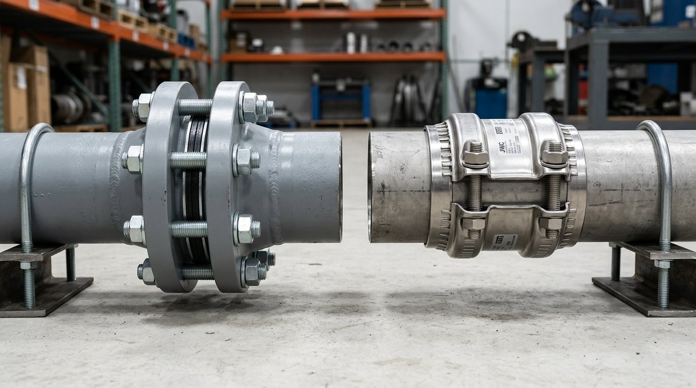
How Each Joint Works
Flanged Joints
A flanged joint connects two pipe ends by bolting together a matched pair of flanges, compressing a gasket seated between their faces. Flanges are either welded to the pipe (weld-neck or slip-on) or threaded. Weld-neck flanges — which bore matches through to the pipe — are the engineering-grade choice for high-pressure or high-cycle service because the weld is at the strongest possible location and stress concentrations are minimised. Slip-on flanges are faster to fit but require two fillet welds and are typically rated lower.
Once bolted, a flanged joint is rigid and fully restrained. The gasket material (spiral-wound, PTFE, ring-type joint, or compressed fibre) must be matched to the fluid, pressure, and temperature. Bolts are torqued in a cross-pattern sequence to achieve uniform gasket compression. Standards such as ASME B16.5 define pressure–temperature classes (Class 150, 300, 600, 900, 1500, 2500) that cover a wide range of industrial applications. At higher classes (Class 600 and above), flanged joints remain the de facto choice for process pipework, refinery headers, and steam systems where pressures are beyond what plain-end mechanical couplings are designed to handle.
Mechanical Couplings
A mechanical coupling connects plain-end pipe without welding, grooving, or threading. The coupling housing — typically stainless or ductile iron — clamps over both pipe ends with a rubber gasket providing the seal. On grip-type couplings such as the JWC MJG/MJGF series, a hardened stainless grip ring inside the housing bites into the pipe wall as the bolts are tightened, making the joint axially restrained (resistant to pull-out) without hot work. On slip-type couplings, the joint seals but permits controlled axial movement for thermal compensation.
The key mechanical difference is where the load is carried. A flanged joint transmits all pipe loads through the rigid metal-to-metal flange face and bolt assembly; the gasket is purely a seal element. A mechanical coupling transmits load through the clamped housing and, for grip types, the grip ring. Pressure capacity is therefore a function of casing thickness and grip-ring engagement — which is why JWC offers a Force-casing variant (MJGF/MJGFL) for higher-pressure service, and why pressure ratings fall as pipe diameter increases.
Pressure Capability: Where the Numbers Sit
This is the dimension that most directly determines which joint is appropriate. Flanged joints at higher ASME classes carry pressures well beyond what any plain-end mechanical coupling currently achieves. However, for the bulk of industrial and marine pipework — moderate-bore water, seawater, and cooling lines running at typical working pressures — mechanical couplings are fully competitive.
JWC Grip Coupling Working Pressures (from catalogue)
| Nominal Diameter | MJG/MJGL — Ship | MJG/MJGL — Industrial | MJGF/MJGFL — Ship | MJGF/MJGFL — Industrial |
|---|---|---|---|---|
| 65A–125A | 14 bar | 28 bar | 16 bar | 32 bar |
| 150A | 12 bar | 24 bar | 16 bar | 32 bar |
| 200A | 8 bar | 16 bar | 12 bar | 24 bar |
| 250A | 8 bar | 16 bar | 10 bar | 20 bar |
| 300A–350A | 7 bar | 14 bar | 10 bar | 20 bar |
| 400A | 6 bar | 12 bar | 8 bar | 16 bar |
Ship ratings carry a ≥4× burst safety factor; industrial ratings ≥2×. Two patterns stand out. First, pressure capacity falls with diameter — a 400A MJGF ship-rated joint (8 bar) carries half the pressure of a 65A–125A MJG (14 bar). Second, the Force casing (MJGF/MJGFL) recovers that capacity at large bores: at 200A, the Force casing adds 50% over the standard grip (12 vs 8 bar ship).
Flanged Joint Pressure Classes (General — ASME B16.5)
ASME B16.5 Class 150 flanges in carbon steel are typically rated around 19–20 bar at ambient temperatures, while Class 300 reaches approximately 50 bar, and Class 600 approaches 100 bar at moderate temperatures. Higher classes (900, 1500, 2500) serve steam headers, high-pressure gas, and refinery process lines where pressures are simply outside the range of mechanical couplings.
The honest crossover: For moderate-bore water and seawater systems running at 10–16 bar industrial working pressure, a JWC MJGF mechanical coupling is pressure-competitive with a Class 150 flange. Above 32 bar (industrial), or on permanently spec-mandated high-pressure process systems, flanges win — and there is no mechanical coupling equivalent at those conditions. Do not use mechanical couplings as substitutes for Class 600+ flanged joints on high-pressure process or steam lines.
Installation: Hot Work, Time, and Labour
The installation difference between a flanged joint and a mechanical coupling is substantial on site, and it compounds across a piping system with many joints.
A weld-neck flange requires a certified welder, a hot-work permit, fire watch, post-weld inspection, and cooling time before hydrostatic testing. In confined spaces, tanks, or occupied facilities, the hot-work permit process adds hours of coordination that have nothing to do with the weld itself. Slip-on flanges reduce one weld but still require hot work. After welding, bolting a flanged pair is straightforward — but the joint cannot be re-entered without breaking all the bolts and replacing the gasket.
A mechanical grip coupling installs on square-cut plain pipe ends with hand tools, no welding equipment, no hot-work permit, no fire watch, and no cooling time. On a documented installation such as the JWC MJG/MJGF range, the process is: mark insertion depth, seat the coupling, and torque the bolts in a cross-pattern to the rated value. The same coupling can be unbolted for inspection and re-torqued, with the gasket often recoverable.
For large systems with many joints — pump rooms, engine-room cooling runs, utility headers — the installation-time advantage of mechanical couplings directly reduces project cost and schedule. Where a hot-work permit is genuinely unavailable (LNG facilities, hospitals, occupied commercial buildings during operation), mechanical couplings are the only viable field joint.
Weight, Space, and Flange Tap-Off Clearance
Flanges add substantial weight. A pair of 200A carbon-steel Class 150 weld-neck flanges plus bolting typically weighs more than 15 kg, and the bolting envelope requires clearance that can conflict with nearby equipment or cable trays. In congested engine rooms and utility decks, flange bolt clearance is a real layout constraint.
Mechanical couplings are lighter and have a smaller radial footprint. A 200A JWC MJGF stainless coupling is a fraction of the weight of a flanged pair. This matters on vessels where deck loading, weight distribution, and pipe-support spacing are engineered to tolerance — and on systems where couplings are specified at regular intervals to absorb thermal movement or vibration rather than being point connectors.
Vibration, Thermal Movement, and Misalignment
Welded flanged joints are rigid. Thermal expansion must be accommodated by expansion loops, bellows, or slip joints elsewhere in the run. Vibration is transmitted through the joint, and any misalignment at installation is locked in permanently. Over years of service, high-cycle vibration on a rigid flanged system can fatigue the welds at the flange neck — a failure mode that requires weld repair or flange replacement.
Mechanical couplings absorb both. Grip-type couplings such as the MJG/MJGF permit angular deflection — up to 4° at 65A–175A and 2° at 200A and above — which accommodates minor installation misalignment without imposing bending loads on the pipe. Slip-type couplings (JWC MJS/MJSF) permit controlled axial movement (5 mm at 15A–175A, 10 mm at 200A–500A), absorbing thermal expansion in-line without separate expansion devices. The rubber gasket provides an inherent vibration-damping layer that a metal-to-metal flanged face does not.
On pump discharge lines, compressor connections, and deck equipment with high vibration, this is often the deciding factor for mechanical couplings even on systems where flanges would otherwise satisfy the pressure requirement.
Maintenance, Re-entry, and Service Life
For systems that require periodic inspection — heat exchanger connections, filter housings, valve bypasses — the re-entry cost difference is significant. Breaking and reflanging a joint means new gaskets, new bolts or bolt inspection, a torque sequence, and a re-test before the line goes back online. On large-bore flanged joints, the bolt count is high and the torque values require calibrated equipment.
A mechanical coupling unbolt procedure is simpler and faster, and the joint can be re-entered multiple times without replacing the gasket on every occasion (subject to inspection). For systems that come offline annually or more frequently, this reduces maintenance labour substantially over a 20-year service life.
Where flanges remain superior is on joints that are never expected to be opened — permanent process connections on refinery headers or chemical plant headers where the gasket compound is set under high flange-face stress and the joint is intended as a lifetime seal. In those cases, the robustness of the flange-face-plus-gasket interface, combined with the higher pressure class available, makes flanges the appropriate choice regardless of installation cost.
Mechanical Coupling vs Flange High Pressure: When to Choose Which
| Criterion | Mechanical Coupling (MJG/MJGF) | Flanged Joint |
|---|---|---|
| Working pressure (industrial) | Up to 32 bar (MJGF, 65A–150A); reduces with bore | Class 150 ~19 bar; Class 300 ~50 bar; higher classes beyond |
| Hot-work permit required | No — plain-end, hand-tool install | Yes — weld-neck or slip-on requires welding |
| Vibration damping | Yes — rubber gasket absorbs vibration | No — rigid metal-to-metal |
| Angular misalignment | Yes — up to 4° at most sizes | No — locked at installation |
| Axial movement (thermal) | Slip-type only (MJS/MJSF); grip types are restrained | Expansion loops required elsewhere |
| Re-entry / maintenance access | Fast — unbolt, inspect, re-torque | Full gasket + bolt replacement |
| Weight and space | Lighter, smaller radial envelope | Heavier, larger bolt clearance required |
| Very high pressure (Class 600+) | Not applicable | Yes — correct choice |
| Permanent, spec-mandated process joint | Not typical spec role | Yes — correct choice |
| Marine class approval | ABS, BV, DNV, KR, LR, NK, RINA | Per flange material and class standard |
| FM/UL fire-protection mandate | Not applicable — no FM/UL listing | Depends on flange spec |
For further detail on grooved-joint alternatives and the overlap with mechanical coupling selection, see our grooved coupling vs flanged joint comparison.
Lifecycle Cost
The capital cost of a mechanical coupling is generally higher than a pair of flanges at the same nominal size. However, installed cost — including the welder, hot-work permit, supervision, inspection, and schedule delay — typically reverses that comparison on large-count systems. On a 50-joint system, the accumulated permit and welding cost for a flanged installation can outweigh the coupling price premium many times over.
Lifecycle maintenance cost further favours mechanical couplings on systems with regular re-entry. Over a 20–25 year service life with periodic maintenance cycles, the lower re-entry labour on mechanical couplings often produces a lower total cost of ownership even on systems where the per-unit coupling price is higher.
The exception is very-high-pressure and permanent-connection systems where the flange class required is not replaceable by any mechanical coupling, and where the joint is designed never to be opened. In those cases, cost comparison is moot — only the flange satisfies the requirement.
FAQ
Can a mechanical grip coupling replace a flange on a pump discharge at 12 bar, 200A?
For an industrial-rated application at 200A and 12 bar, a JWC MJGF grip coupling is rated at 12 bar ship (≥4× safety factor) and 24 bar industrial (≥2× safety factor) — it is pressure-competitive. Whether it is the right choice also depends on whether a hot-work permit is available, whether the joint needs re-entry access, and what class approval the vessel or facility requires. If the system is ABS, BV, DNV, KR, LR, NK, or RINA classed, check the type approval for the specific size and service line — all seven societies have approved the JWC grip range, but certified size ranges vary per society.
When should I not use a mechanical coupling and specify a flange instead?
Specify flanges where: (1) working pressure exceeds the coupling’s rated capacity at that bore (above ~32 bar industrial for small bores, less for large bores); (2) the system is a high-pressure process or steam line requiring ASME Class 600 or above; (3) the project specification explicitly mandates flanged joints; (4) FM or UL listing is required for a fire-protection system — JWC couplings do not hold FM or UL approval.
Key Takeaways
- Pressure capability is the primary decision driver — JWC MJGF grip couplings reach up to 32 bar industrial at small bores (65A–150A) and are pressure-competitive with Class 150 flanges on many moderate-bore lines. Above 32 bar, or where Class 300+ flanges are mandated, flanges are the correct choice.
- No hot-work permit is the strongest argument for mechanical couplings — where welding is prohibited or impractical, mechanical couplings are the only field-installable plain-end joint, with no compromise on pressure performance in their rated range.
- Flanges are the honest answer at very high pressure and on permanent process connections — do not stretch mechanical couplings beyond their rated capacity, and do not specify them as substitutes for spec-mandated flange classes.
- Vibration, thermal movement, and misalignment tolerance favour mechanical couplings — the inherent flexibility of a rubber-gasketed coupling is a real engineering advantage on pump connections, compressor lines, and thermally active runs.
- Re-entry and lifecycle cost often favour mechanical couplings on maintained systems — particularly on multi-joint systems where the accumulated welding cost for flanges exceeds the coupling price premium, and where annual maintenance cycles reduce the flanged-joint advantage of lower per-unit capital cost.
About David Phee Enterprise
David Phee Enterprise is the exclusive Singapore distributor for Jeong Woo Coupling (JWC) and a long-established supplier of Aju, Romacon, and Smith-Blair couplings, repair clamps, and expansion joints. Operating from Empire Technocentre in Kaki Bukit, DPE supplies ship chandlers, shipyards, and industrial contractors across Singapore, Malaysia, and Indonesia — stocking the JWC grip range (MJG, MJGL, MJGF, MJGFL) in SUS 304 and SUS 316, with pressure-class and gasket selection support for marine and high-thrust applications. For datasheets, class-approval certificates, and technical guidance on mechanical coupling vs flange high-pressure selection, contact DPE at davidphee.com.