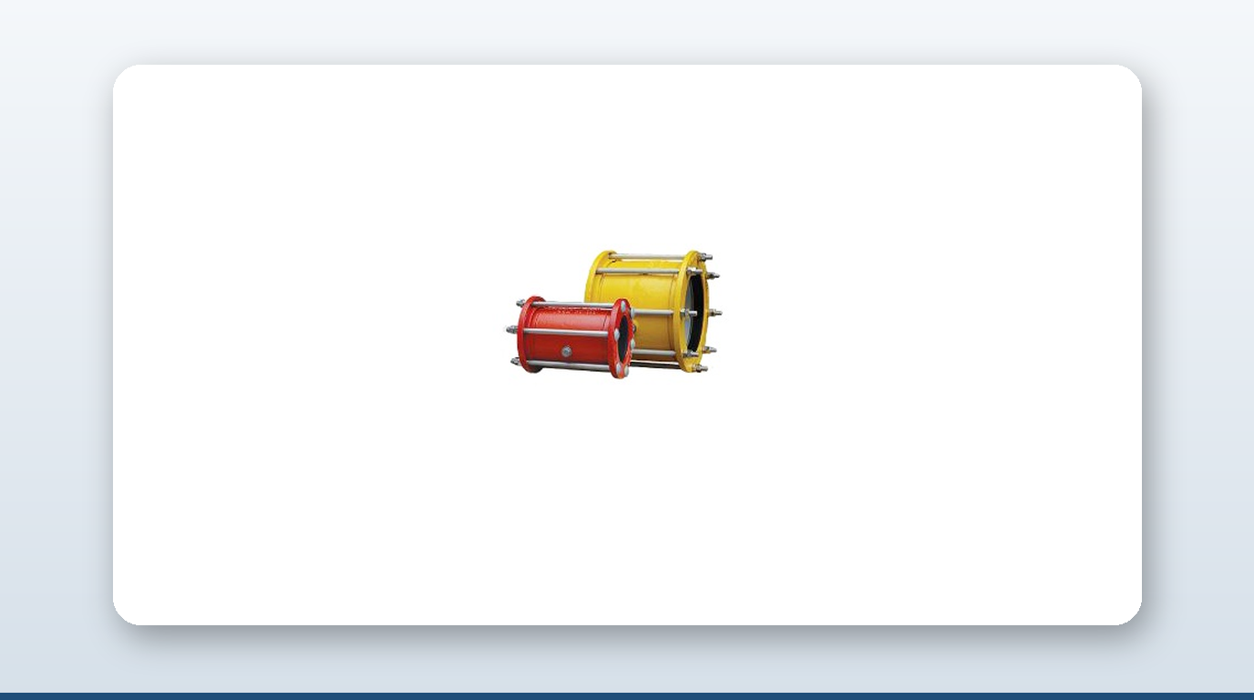
On a centrally-cooled commercial vessel, the fresh water cooling loop is the quieter sibling of the seawater circuit — but getting the ship cooling water piping coupling selection wrong still costs a chief engineer a dry-dock repair. Inhibited fresh water runs two closed loops, high-temperature and low-temperature, both of them Class III piping sitting inside Category A machinery space, both expecting type-approved couplings and the right gasket chemistry.
This guide covers the HT/LT loop architecture, the water chemistry that keeps the system friendly, why EPDM is the only defensible gasket choice on the fresh water side, and how coupling selection changes section by section from the engine jacket to the header tank. This is the closed-loop freshwater side specifically — distinct from seawater material selection, which runs its own corrosion and biofouling story.
HT and LT Loops — Two Circuits, One Job
A modern centrally-cooled vessel runs two distinct closed fresh water loops in series with the seawater intake, meeting only at the central cooler:
| Loop | What it cools | Typical engine inlet (°C) | Typical engine outlet (°C) | Pressure (bar) |
|---|---|---|---|---|
| HT (high-temperature) FW | Main engine cylinder jackets, cylinder covers, exhaust valves, turbochargers | 65–80 | 85–95 (max ~90 typical limit) | 2–4 |
| LT (low-temperature) FW | Lube oil cooler, charge-air (scavenge) cooler, fresh water generator, A/C condenser, alternator | 36–38 (controlled) | 42–48 | 2–4 |
The HT and LT circuits share a common expansion (header) tank but run separate pumps and separate temperature-control valves. The central cooler — a titanium-plate or shell-and-tube heat exchanger — is the only point where either circuit sees the seawater loop. Every other heat-exchange surface on the vessel sees clean, inhibited fresh water: no chloride, no oxygen ingress past the deaerated header tank, no biofilm, no marine growth. That is the whole reason fresh water joints typically last 15–25 years against 5–10 years on the seawater side.
Water Chemistry: What Keeps the Loop Friendly
The inhibited fresh water loop runs inside tight chemistry windows. Exceed them and corrosion, scale, microbiological fouling or elastomer breakdown follow predictably:
| Parameter | Make-up water spec | Circulating loop spec | Why it matters |
|---|---|---|---|
| Chloride (Cl⁻) | <50 ppm | <100 ppm (some OEMs <50) | Above 100 ppm, nitrite inhibitor breaks down and 316L pitting starts; MAN sets 50 mg/L preferred |
| Total hardness (as CaCO₃) | <100 ppm | <170 ppm | Above 170 ppm, scaling on cylinder liners and heat exchanger surfaces reduces heat transfer 10–20% |
| pH | 6.5–8.5 (drinking water grade) | 8.5–10 (post-treatment) | Below 7 = acidic attack on copper alloys and cast iron; above 11 = aluminium attack and nitrite inefficient |
| Conductivity | <500 µS/cm | <2,000 µS/cm | Proxy for total dissolved solids; high conductivity drives electrolytic corrosion |
| Sulfate (SO₄²⁻) | <100 ppm | <100 ppm | Drives sulfate-reducing bacteria, leading to microbiologically induced corrosion |
| Dissolved O₂ | n/a (saturated) | <0.1 ppm (deaerated via header tank) | Nitrite consumes residual O₂; uncontrolled ingress wastes inhibitor and drives pitting |
Distilled water from the fresh water generator is the preferred make-up source on most commercial vessels, since it gives near-zero chloride and hardness by construction. The treatment market splits into three families: nitrite/borate (the dominant marine choice — products like Wilhelmsen Rocor NB at 1,000–2,400 ppm NO₂⁻ and Drew Marine Maxigard), molybdate (a thermally stable premium alternative for mixed-metallurgy systems, 5–10× the cost per kg of nitrite), and tannin/polymer treatments (rare on marine duty, inadequate protection at marine temperatures). Glycol is dosed at 25–50% on cold-route or laid-up vessels for freeze protection, but a 50% glycol mix drops thermal conductivity roughly 30% and heat capacity roughly 20%, so the engine runs 2–5°C warmer for the same heat load. Glycol is fully compatible with nitrite/borate chemistry and EPDM gaskets but degrades NBR over time.
EPDM vs NBR — Not a Style Choice, a Failure Point
The nitrite/borate inhibitor chemistry, the glycol dosing on cold-route vessels, and the 85–95°C jacket-water outlet temperature combine to make EPDM the only defensible gasket choice on the fresh water side. EPDM Grade E handles −40°C to +150°C, glycol and nitrite chemistry, and steam exposure, and is rated to 20 years of service at sustained 90°C cyclic load. NBR, by contrast, fails in 2–5 years in the HT loop under the same chemistry and temperature — the nitrite/glycol combination and the sustained high temperature break it down well before EPDM shows comparable wear. Any fresh water cooling tender should quote EPDM as default; mixing NBR housings into the same loop puts the whole system on a failure timer.
Class Society Rules for Class III FW Cooling
All six major IACS societies harmonise pipe classification under IACS UR P2, in force from 1 January 2025. Fresh water cooling sits in Class III across every one of them — design pressure ≤7 bar and design temperature ≤170°C for “other media,” the lowest-friction bracket in the table:
| Society | Reference | FW cooling joint rules | Cat-A machinery-space restriction |
|---|---|---|---|
| ABS | Rules Pt.4 Ch.6 §4 — Piping Systems | Class III: slip-on, grip-type, machine-grooved, rigid grooved all permitted with Type Approval | “Approved fire-resistant types only” inside Cat-A — ISO 19921 wet endurance |
| DNV | Pt.4 Ch.6 Sec.9 — Pipe couplings other than flanges | No OD restriction on Class III — couplings freely used at any diameter | Fire endurance class “wet” required in pump rooms, open decks, Cat-A machinery |
| LR | Pt.5 Ch.12 Sec.10 — Piping Design Requirements | Mechanical joints permitted on Class III FW cooling subject to LR Type Approval | Fire endurance required where joint sits adjacent to fuel/oil |
| BV | NR467 Pt.C Ch.1 Sec.10 — Piping Systems | Slip-type slip-on permitted on deck at design pressure ≤10 bar; full type-approval range on Class III FW | Fire-resistance per IACS UR P2 inside Cat-A |
| ClassNK | Pt D Ch.8 — Piping | Shielded couplings for FW cooling permitted; corrosion-resistant metal parts plus qualifying shear test | “Fire resistant type” required in Cat-A; ISO 19921 equivalent |
| KR | Pt 5 Ch 6 — Piping Systems | Harmonised with IACS UR P2 — Class III FW cooling permits the full mechanical-joint family | Same Cat-A fire-resistance requirement |
The practical takeaway across all six: for fresh water cooling, the joint itself is allowed — the elastomer and fire endurance certification are the actual gate. A coupling with an EPDM Grade E gasket plus ISO 19921 wet endurance certification is unrestricted across all six societies on Class III FW cooling. Without that wet-endurance cert, the joint is still allowed outside Category A, but a fitter will be told to replace it if it sits inside that space.
Coupling and Gasket Selection by Loop Section
Coupling and gasket choice shifts by section as temperature and duty change along the loop:
| Section | Typical pipe material | Working temp | Coupling choice | Gasket |
|---|---|---|---|---|
| HT engine jacket inlet | Mild steel coated, occasionally Cu-Ni 90/10 | 65–80°C | Grip-type or rigid grooved | EPDM Grade E |
| HT engine jacket return | Mild steel coated | 85–95°C | Flexible slip-type to absorb thermal growth | EPDM Grade E (NBR will fail) |
| HT pump suction | Mild steel coated | 80°C | Rigid grooved plus flexible expansion joint | EPDM |
| LT pump suction | Mild steel coated | 36–38°C | Slip-type or grip-type | EPDM or NBR (NBR borderline OK at this temperature) |
| LT branch lines (LO cooler, A/C, FWG) | Mild steel coated, occasionally galvanised | 36–48°C | Slip-type | EPDM preferred |
| Header / expansion tank fill line | Mild steel coated | Ambient–60°C | Slip-type | EPDM |
| Central cooler FW side connections | Mild steel / SS304 stub flanges | 36–95°C | Flange-adapter coupling | EPDM (matches central cooler gasket spec) |
Common Failure Modes and Repairs
The fresh water loop is a slower bleed than seawater, but the joints still see thermal cycling, vibration and gradual elastomer ageing — a 25-year vessel runs roughly 150,000 thermal cycles on the HT circuit alone at 5–10 cycles per day. Known failure modes and their standard repair path:
- – Gasket compression set at the HT manifold — the most common failure. EPDM Grade E is rated 20 years at sustained 90°C; below-spec EPDM or NBR contamination fails in 2–5 years. Repair: re-torque to factory spec, then swap the gasket if leaking persists, then move to a higher Shore-A EPDM-HT compound if it still leaks.
- – Cavitation pinhole on jacket water return at the TC valve throttle drop — a sudden pinhole from bubble collapse against the pipe ID. Repair: a Romacon or Smith-Blair repair clamp over the pinhole, with full pipe-section replacement at the next dry-dock.
- – Cold-side flange weep at the central cooler — thermal cycling racks bolt preload and creates gasket creep. Repair: re-torque first, replace the gasket, or move to a permanent flange-adapter coupling.
- – Header tank freeze crack on cold-route vessels (Baltic, North Atlantic) — a vented header tank freezes if the vessel lays up without a glycol dose. Repair: a repair clamp over the cracked seam, with a recommendation to dose 25–35% glycol at lay-up.
- – Operator failure to dose inhibitor — silent corrosion. Pump bowls, carbon-steel headers and pre-cooler stub flanges general-corrode over 6–24 months, detected at survey as light brown sludge in FW samples. Remediation: full system flush and retreatment to target nitrite residual.
- – Aluminium charge-air cooler corrosion at pH above 9.5 from over-dosing inhibitor on a system with aluminium components. Repair: drain, neutralise, refill at pH 8.5–9.
Key Takeaways
- – Fresh water cooling runs two closed loops — HT at 85–95°C jacket-water outlet and LT at 42–48°C outlet — sharing one header tank but separate pumps and control valves.
- – The loop is Class III across all six IACS societies (≤7 bar, ≤170°C), which permits slip-type, grip-type, machine-grooved and rigid grooved couplings with Type Approval.
- – EPDM Grade E is rated to 20 years at sustained 90°C cyclic load; NBR fails in 2–5 years in the HT loop under the same nitrite/glycol chemistry and temperature.
- – Inhibitor breakdown — nitrite dropping below target residual — is the #1 fresh water failure mode and drives the carbon-steel corrosion that shows up later as gasket and flange leaks.
- – Chloride must stay under 100 ppm in the circulating loop (some OEMs specify under 50 ppm); above that, nitrite inhibitor breaks down and 316L pitting starts.
- – Fresh water joints typically last 15–25 years versus 5–10 years on the seawater side, because the central cooler is the only point where either loop touches raw seawater.
About David Phee Enterprise
David Phee Enterprise is the exclusive Singapore distributor for JWC pipe couplings, stocked at Empire Technocentre, Kaki Bukit for same-day delivery, alongside Romacon repair clamps and Smith-Blair couplings for fresh water HT/LT cooling-loop repairs and A-Ju expansion joints for pump-suction and pump-discharge vibration absorption on the same loop. For coupling specs or certification documentation on any of these ranges, contact DPE or browse the full catalogue at davidphee.com. Related reading: NBR, EPDM and Viton gaskets explained and seawater pipe coupling material selection.