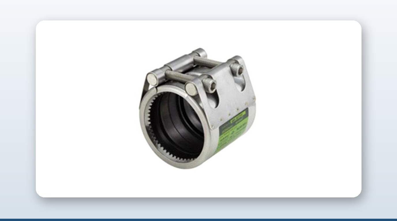
Marine HVAC and compressed air get lumped together as “auxiliary” systems on an engine room arrangement plan, but marine HVAC compressed air piping sits at opposite ends of the coupling market. Chilled-water HVAC is the single biggest grooved-coupling sale on a vessel — large diameter, long runs, low pressure, and a market Victaulic has owned for thirty years. Compressed air is almost the reverse: high pressure, short runs, and a joint regime that stays welded by both code and habit.
This article maps both systems — HVAC chilled water, condenser water and reheat on one side, starting air, service air and control air on the other — against the class-society rules that decide where a mechanical coupling is even allowed, and where it is actually won.
Two Systems, Opposite Coupling Markets
The two systems differ on every axis that matters for joint selection:
| Axis | HVAC chilled water | Compressed air |
|---|---|---|
| Pressure | Low (3–10 bar working, 16 bar test) | High (7 bar service, 30–40 bar starting) |
| Diameter | Large (DN50–DN500+) | Small (DN15–DN65 typically) |
| Length of run | Very long (whole vessel) | Short (engine room only) |
| Vibration source | Chiller compressors and pumps | Reciprocating air compressor |
| Joint preference | Grooved mechanical (Victaulic dominant) | Welded socket/butt, flanged at valves |
| DPE addressable | Cross-sell only (Victaulic-spec’d by default) | Repair-clamp only (welded primary, no coupling) |
HVAC Chilled Water — System Anatomy
The central architecture on any vessel with mechanical air conditioning above roughly 5,000 GT — cruise ships, ferries, OSVs, FPSO accommodation, large naval auxiliaries — is a central chilled-water plant feeding multiple secondary distribution loops:
| Loop / branch | Typical fluid | Pressure (bar) | Temperature (°C) | Pipe diameter typical |
|---|---|---|---|---|
| Primary chiller loop (chiller ↔ central manifold) | Fresh water + optional 20% glycol | 4–10 working / 16 test | 6–8 supply / 12–14 return | DN150–DN500 |
| Secondary distribution (manifold ↔ AHUs/FCUs) | Fresh water + optional glycol | 3–6 working | 6–10 supply / 12–14 return | DN50–DN200 |
| Condenser water loop (chiller ↔ sea water heat exchanger) | Sea water or LT fresh water | 3–6 working | 30–38 in / 36–42 out | DN150–DN400 |
| Refrigerant (within chiller package) | R-134a / R-1234ze / R-513A / ammonia / CO₂ | 15–40 (compressor side) | −10 to +50 | DN15–DN80 |
| Hot water (heating coil reheat) | Fresh water (sometimes thermal oil) | 3–6 working | 60–80 supply | DN50–DN150 |
| Brine (refrigerated cargo) | Glycol/water 35–50% | 3–6 working | −10 to −25 supply | DN80–DN300 |
On a large cruise vessel, multiple 4,000–6,000 kW centrifugal chillers feed 2-pipe or 4-pipe distribution to thousands of fan-coil units, with total chilled-water piping running into the tens of kilometres per ship.
Compressed Air — Three Pressure Tiers
The compressed-air suite on a typical merchant ship runs three distinct pressure tiers off two or three reciprocating air compressors:
| Branch | Pressure | Pipe diameter typical | Pipe material | Joint method | DPE addressable |
|---|---|---|---|---|---|
| Main starting air | 30 bar (some MAN B&W up to 40 bar) | DN50–DN80 | Seamless carbon steel SCH 80 (Class I) | Welded socket/butt; flanged at valves | No — Class I welded mandatory |
| Emergency starting air | 30 bar | DN40–DN50 | Seamless CS SCH 80 | Welded; flanged | No |
| General service air | 7–8 bar | DN25–DN50 | CS galvanised or SS | Welded/threaded/occasional flange | Marginal — Class III, welded by habit |
| Control air (filtered) | 7 bar | DN10–DN20 | Stainless steel tube | Compression fittings | No — tubing, not pipe |
| Working air (deck tools) | 7 bar | DN25–DN50 | CS | Threaded/welded | Marginal |
SOLAS Ch.II-1 Reg.26 mandates at least two main air compressors capable of recharging receivers within one hour, plus one independent emergency compressor.
Class Society Rules: Where the Joint Line Falls
IACS UR P2.2 — adopted essentially verbatim by ABS, DNV, LR, BV, NK and KR — divides ship piping into three classes on the “other media” row that covers both HVAC water and compressed air:
| Class | Design pressure (bar) | Design temperature (°C) | Joint regime |
|---|---|---|---|
| Class I | > 40 | > 300 | Welded butt or socket only; flanged at valves; no mechanical couplings |
| Class II | > 16 to ≤ 40 | > 200 to ≤ 300 | Welded preferred; mechanical joints by Type Approval, OD > 60.3 mm only, with fire endurance in Cat-A |
| Class III | ≤ 16 | ≤ 200 | Welded, flanged or mechanical all allowed with Type Approval; fire endurance required in Cat-A |
Mapped against the actual sub-systems:
| Sub-system | Pressure / Temp | IACS Class | Joint allowed? |
|---|---|---|---|
| HVAC chilled water primary | ≤10 bar / ≤14°C | Class III | Yes — grooved, slip-on, all mechanical with Type Approval |
| HVAC condenser water | ≤6 bar / ≤42°C | Class III | Yes |
| HVAC reheat/hot water | ≤6 bar / ≤80°C | Class III | Yes |
| Refrigerant (ammonia, cargo) | varies | Class I or II — IGC Code | No mechanical — toxicity |
| Starting air (30 bar) | 30 bar / ≤80°C | Class II (sits at threshold) | Type Approval + OD > 60.3 mm required; in practice welded only |
| Service air (7 bar) | 7 bar / ≤60°C | Class III | Yes — but rarely deployed |
The convergence point across every IACS member: chilled-water HVAC is Class III with mechanical joints permitted on Type Approval, and starting air is Class II with welded joints in practice everywhere. The HVAC coupling spec is the contestable surface; starting air is closed to mechanical couplings on every society.
Why Grooved Couplings Dominate HVAC
Grooved couplings won the chilled-water HVAC market for four structural reasons:
1. Vibration isolation comes free. The ductile-iron grooved housing absorbs sound energy and the elastomer gasket compresses without bottoming, forming a built-in vibration absorber — eliminating the need for a standalone vibration eliminator at every pump. 2. Yard labour cost. Welding DN150–DN300 carbon-steel chilled-water headers versus roll-grooving and bolting is a 3–5× labour productivity advantage per joint. Across 20+ km of HVAC piping on a cruise ship, that is the difference between two weeks and two months of yard labour. 3. Disassembly for service. Chillers and AHUs need 20–30 year operational lifetimes with periodic teardowns for coil cleaning and refrigerant retrofits. Grooved couplings break apart in 10 minutes per joint without cutting or re-welding. 4. Fire endurance is solved. Fire-tested grooved coupling architectures satisfy surveyors at A-rated boundary crossings — one of only two joint architectures (the other being all-welded) that does.
Slip-on couplings such as JWC MJG/MJS are technically permitted on Class III chilled water but are rarely specified on cruise newbuilds, because the slip-on housing relies on gasket compression alone rather than a machined groove, and the cruise/passenger market has standardised on grooved for thirty-plus years. On commercial cargo, tanker and bulker HVAC — smaller systems serving 10–50 cabins rather than 1,500–3,000, with pipe diameters typically DN25–DN100 — slip-on couplings compete on price since the yard does not pay for grooving infrastructure in the first place.
Why Compressed Air Stays Welded
Starting air at 30 bar, under severe reciprocating-compressor vibration and with a high-consequence failure mode, is the most welded-conservative system on the vessel after fuel oil, for three reinforcing reasons:
1. Vibration fatigue. Multi-stage reciprocating compressors generate harmonic pulsations down the discharge piping; slip-on couplings lose preload under fatigue cycling at 30 bar within 5–10 years of 100,000+-cycle service, while welded joints survive indefinitely. 2. The Class II threshold sits exactly at the system pressure. 30 bar falls in the Class II band (16–40 bar), and IACS UR P2.7 limits mechanical joints in Class II to OD > 60.3 mm — exactly the size band of starting-air pipe (typically DN65). Surveyors interpret this strictly on a safety-critical system. 3. Yard practice is welded by habit. Engine OEMs (MAN ES, WinGD, Wärtsilä) draw starting-air arrangements welded, and no yard deviates.
Service and control air at 7 bar is Class III and grooved coupling could technically be specced, but almost never is — the pipe sizes are too small for grooved economics, the control-air leg runs stainless tube with compression fittings rather than pipe, and yards already have the welded-pipe trade flow set up from starting-air work.
The one place couplings legitimately enter compressed air is emergency repair. A pinhole leak on the 30-bar starting-air manifold in service cannot be welded, since the vessel must keep starting capability — a high-pressure split-barrel repair clamp is the survival tool here, with stainless repair clamps rated to 300 bar giving comfortable margin over the 30-bar line.
Key Takeaways
- – HVAC chilled water is Class III (≤16 bar, ≤200°C) across every IACS society and permits grooved, slip-on and all mechanical joints with Type Approval; starting air at 30 bar sits in Class II, where mechanical joints need OD > 60.3 mm approval and are welded in practice regardless.
- – Grooved couplings dominate cruise-ship HVAC because they give free vibration isolation, a 3–5× yard labour advantage over welding, 10-minute disassembly for service, and solved fire endurance at A-rated boundaries.
- – Slip-on couplings compete on price only on smaller commercial cargo/tanker/bulker HVAC systems (DN25–DN100), not on cruise-scale chilled-water headers where grooved is the 30-year incumbent.
- – SOLAS Ch.II-1 Reg.26 requires at least two main starting-air compressors able to recharge receivers within one hour, plus an independent emergency compressor.
- – The only coupling that legitimately touches compressed air is an emergency repair clamp over an in-service pinhole — a stainless split-barrel clamp rated to 300 bar comfortably covers a 30-bar starting-air line.
- – Control air runs stainless steel tube with compression fittings, not pipe with couplings, so it carries no coupling market at all.
About David Phee Enterprise
David Phee Enterprise is the exclusive Singapore distributor for JWC pipe couplings, stocked at Empire Technocentre, Kaki Bukit for same-day delivery, alongside A-Ju expansion joints for chiller and condenser pump-discharge vibration isolation and Romacon repair clamps for in-service HVAC or compressed-air leaks. On the 30-bar starting-air system itself, the line stays fully welded by class rule, so Romacon’s high-pressure repair clamp is the only mechanical product that touches it, and only as an emergency patch pending the next dry-dock. For coupling specs or certification documentation on any of these ranges, contact DPE or browse the full catalogue at davidphee.com. Related reading: central fresh water cooling coupling selection and classification societies DNV, ABS and LR explained.