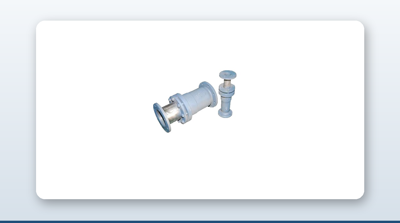
Steering gear is the single most consequential hydraulic system on a commercial vessel — a ship that loses steering with full propulsion runs aground — and that consequence shapes every hydraulic steering gear piping coupling decision on board. The pressure side of the loop is welded-and-precision-fit territory by default, locked out by SOLAS and IACS rules that treat a wrong joint here as a life-safety issue, not a maintenance inconvenience. The opportunity for a mechanical coupling is real but narrow, and it sits entirely on the low-pressure side of the pump skid.
This article works through the pressure regimes across marine hydraulics, the SOLAS and IACS rules that decide where welding is mandatory, and the specific low-pressure lines where a mechanical joint is both permitted and practical.
Pressure Regimes Across the Hydraulic Envelope
Marine hydraulic systems span a wide pressure spectrum because the actuators they serve do very different jobs. SOLAS II-1 Reg.29 §2.2 sets design pressure at a floor of 1.25× the maximum working pressure expected under operational conditions:
| Sub-system | Typical working pressure (bar) | Design pressure floor (bar) | Architecture notes |
|---|---|---|---|
| Main steering gear (rotary vane/ram) | 140–210 | 175–260 | Closed loop; two independent power units; bypass/cross-flow valves for emergency operation |
| Auxiliary/emergency steering | 140–210 (same loop) | 175–260 | Second pump unit on the same actuator, or a fully separate actuator on tankers ≥10,000 GT |
| Hatch cover hydraulic power unit | 170–200 working | 215–250 design | Stainless rod or sleeve on cylinders for corrosion; pressurised only on operation cycle |
| Deck crane | 250–320 | 315–400 | Load-sensing pumps to save energy |
| Watertight door (sliding type) | 100–150 | 125–190 | Bridge-controlled closure within 60 seconds per SOLAS II-1 Reg.13 |
| Mooring winch | 175–250 | 220–315 | Often shares an HPU with cranes on smaller vessels |
| Steering gear hydraulic return/make-up | < 7 (typically 1–3) | 7–16 | Header tank, drain line back to reservoir — the DPE opening |
| HPU suction/fluid storage/drain | < 1 (atmospheric/gravity) | < 7 | Make-up tank to pump suction — cleanliness-controlled but pressure-trivial — the second DPE opening |
A pipe sized for 200 bar working pressure carries heavier wall thickness, gets a butt-welded socket and flanged connection at the actuator, and uses precision DIN 2353 compression couplings or ORFS (O-Ring Face Seal) fittings for small-bore tap-offs, rated up to 420 bar. A pipe on the return side at 2–3 bar is lighter-wall carbon steel, flanged at bulkheads, with slip-on couplings on the runs between them. The same physical envelope holds both regimes — the discipline is reading which line is which on the schematic before proposing a joint.
SOLAS II-1 Regulation 29 — The Redundancy Mandate
SOLAS Chapter II-1 Regulation 29 is the operational rulebook, and several clauses drive joint specification directly:
- – §2.2 — Design pressure: at least 1.25× maximum working pressure — the first number to read off any steering schematic.
- – §2.3 — Relief valves: every isolatable section that can generate pressure must carry a relief valve sized to avoid an undue rise above design pressure.
- – §6.1 — Main/auxiliary split: main and auxiliary gear must be arranged so a single failure of one does not disable the other — why most merchant ships above 100 GT carry two pumps on a single actuator rather than a separate auxiliary actuator.
- – §8 — Rudder rate: main steering gear must move the rudder from 35° on one side to 35° on the other at maximum service speed in not more than 28 seconds at the ship’s deepest seagoing draught.
- – §12 — Hydraulic fluid maintenance: arrangements to maintain fluid cleanliness; a low-level alarm on each reservoir, audible and visual, on the bridge and in the machinery space; a fixed storage tank permanently connected and sized to recharge at least one power actuating system including its reservoir.
- – §16 — Tankers ≥10,000 GT and chemical/gas carriers: either two independent power actuating systems or two identical systems acting simultaneously, with loss of fluid from one automatically detected and the defective system automatically isolated; steering capability must be restored within 45 seconds of a single failure on tankers 10,000 GT to 100,000 DWT.
Every joint on the pressure side sits inside a SOLAS-mandated redundancy chain. The surveyor’s view is that the joint should not fail in the first place — which is exactly why welded and precision compression fittings dominate the pressure side, leaving the return side as the only place to sell a slip-on coupling.
IACS UR M42 and UR P2 — Where the Class Line Falls
IACS Unified Requirement M42 is the binding rulebook for steering gear specifically, and it pulls joints, valves, flanges and fittings for steering gear out of the ordinary hydraulic piping regime — meaning any mechanical coupling proposed for a steering gear line needs a Type Approval Certificate that explicitly cites steering gear service, not just “hydraulic systems generally.” Hose burst pressure must be at least 4× design pressure for hydraulic hoses in the steering gear system.
IACS UR P2 governs piping generally, with a specific carve-out at §1.2.2: “Hydraulic fluid systems, except those for steering gear, require individual consideration by each Classification Society.” Steering gear is separated out and held to UR M42’s stricter regime. The Class I/II/III thresholds that apply:
| Class | Design pressure threshold | Design temperature threshold | Joint families permitted |
|---|---|---|---|
| Class I | > 16 bar (hydraulic/other media) | > 150°C | Welded primary; mechanical joints only with Type Approval explicitly covering Class I |
| Class II | ≤ 16 bar and ≤ 150°C | — | Welded preferred; mechanical joints permitted with Type Approval — slip-on is the workhorse |
| Class III | ≤ 7 bar and ≤ 60°C | — | Welded/flanged/mechanical all permitted; lowest surveyor friction |
Reading this against steering gear specifically: the pressure side (140–210 bar working, 175–260 bar design) is Class I by pressure, so welded primary with precision tube fitting at the actuator and valve block interfaces — slip-on couplings are essentially excluded. The return/drain/make-up side (<7 bar) is Class II or III, where mechanical joints are permitted with Type Approval. The same split applies to hatch-cover and crane HPU circuits: pressure side welded, return/suction/drain side open to mechanical joints.
Why the Pressure Side Stays Welded
Five reinforcing forces pin the pressure side to welded and precision-fit joints:
1. Fatigue from cyclic loading. Rudder movement is continuous at sea — autopilot corrections every 2–5 seconds — subjecting the steering gear to millions of pressure cycles per voyage. Welded joints, properly executed, carry fatigue endurance limits set by the parent material, which is why class rules mandate qualified welding procedures and 100% non-destructive testing on Class I welds. 2. High-pressure burst and pull-out resistance. Restrained grip-type mechanical couplings are typically rated 70–100 bar, with high-pressure variants reaching 150–250 bar. The steering gear working envelope (140–210 bar) sits at the outer edge of what restrained mechanical couplings can carry, and the design envelope (175–260 bar) exceeds it — welded, flanged or precision tube fittings are the only joints with headroom. 3. Oil cleanliness targets. Steering gear hydraulic systems target ISO 4406 cleanliness codes from 18/16/13 down to 16/14/11 for servo-controlled systems. Welded joints have no crevices for contamination ingress; slip-on couplings with rubber gaskets can shed elastomer particulate as the gasket degrades, which disqualifies them from any line upstream of the reservoir suction filter. 4. Vibration from pump pulsation. Variable-displacement axial-piston pumps generate pressure ripple at piston-passing frequency, typically in the 100–300 Hz band, which excites pipe-wall flexure. Welded socket joints with stress-relieving fillet detail hold up under this; slip-on rubber-gasketed joints can chatter and develop micro-leaks at the gasket lip. 5. Class Type Approval economics. A mechanical joint Type Approval Certificate for steering gear specifically is expensive and rarely pursued — most coupling TACs cover “hydraulic systems generally” but carve out steering gear, hatch covers and watertight doors as out of scope, since manufacturers don’t want to underwrite the SOLAS life-safety exposure. Even where the physics would allow a slip-on coupling, the paperwork often does not.
The Joint Map — Where Mechanical Couplings Actually Fit
Mapping joint type against where it actually lives on the schematic:
| Joint type | Where it lives | DPE-relevant fit |
|---|---|---|
| Butt-welded socket | Steering gear pressure header, pump skid to actuator; HPU pressure manifolds | No coupling sale |
| Flanged (RF/FF, ASME B16.5) | Pump skid inlet/outlet, actuator interface, accumulator connection | Flange-end couplings only on rare service-water tie-ins |
| DIN 2353 / ORFS precision compression | Small-bore tap-offs to gauges, accumulators, pilot lines | No DPE product — specified at precision tube-fitting level |
| Slip-on grip-type, fire-tested (Class II) | Low-pressure return lines inside the steering flat; hatch-cover HPU return | JWC MJSG with Fire-Resistant Cover — Class II Type Approved, ISO 19921 fire-tested |
| Slip-on machine-grooved (Class II/III) | HPU make-up and drain lines; non-fire-exposed equipment room hydraulic runs | JWC MJG |
| Sleeve/slip-type coupling (Class III) | Pump-room HPU drains outside Cat-A | JWC MJS — limited, not for Cat-A primary joints on flammable fluid |
| Rubber expansion joint (Class II/III) | Pump skid suction; pump-to-reservoir return; vibration isolation | A-Ju EJD — NBR or FKM lining, <90°C, <16 bar |
| Repair clamp (in-service rescue) | Pinhole leaks on return lines, drain piping, HPU shell connections | Romacon Snaplock/Universal Wide Range |
A typical steering gear flat carries roughly 8–14 metres of high-pressure piping between pump skids, manifold and actuator — no coupling sale at all — against 6–10 metres of low-pressure return/drain piping, 3–5 metres of fluid make-up and storage line, and 2–4 metres of vent/overflow/spillage drain, all of which sit in Class II/III territory where a mechanical joint is both permitted and practical. Across hatch covers, deck cranes and watertight doors on the same vessel, the total mechanical-eligible hydraulic piping on a single new-build can run 80–150 metres.
Key Takeaways
- – SOLAS II-1 Reg.29 §2.2 sets steering gear design pressure at 1.25× maximum working pressure, putting the main loop at 140–210 bar working and 175–260 bar design.
- – IACS UR P2 §1.2.2 explicitly carves steering gear hydraulics out of general hydraulic piping rules and holds it to the stricter UR M42 regime, which requires a Type Approval Certificate that names steering gear service specifically.
- – The Class I/II/III thresholds split steering gear hydraulics cleanly by pressure: above 16 bar is Class I (welded primary), at or below 16 bar and 150°C is Class II (mechanical joints permitted with Type Approval), and at or below 7 bar and 60°C is Class III (lowest friction).
- – Restrained mechanical couplings typically cap out around 70–250 bar depending on design, while the steering gear working envelope runs 140–210 bar — right at or past that ceiling, which is why welded and precision compression fittings dominate the pressure side.
- – Steering gear hydraulic fluid targets ISO 4406 cleanliness codes of 18/16/13 to 16/14/11, and rubber-gasketed slip-on couplings can shed elastomer particulate that disqualifies them from any line upstream of the suction filter.
- – The mechanical-coupling opening on a typical vessel’s steering gear flat is 15–20 metres of low-pressure return, make-up and drain piping — versus zero on the 8–14 metre high-pressure header.
About David Phee Enterprise
David Phee Enterprise is the exclusive Singapore distributor for JWC pipe couplings, stocked at Empire Technocentre, Kaki Bukit for same-day delivery, alongside A-Ju expansion joints for HPU suction and return vibration isolation and Romacon repair clamps for emergency, in-service containment of a pinhole leak on a low-pressure hydraulic return line. The high-pressure steering gear ram circuit itself runs welded and precision tube fittings that DPE doesn’t carry — the coupling business applies only to the low-pressure return, make-up and drain lines around it. For coupling specs or certification documentation on any of these ranges, contact DPE or browse the full catalogue at davidphee.com. Related reading: mechanical coupling vs flange and pipe coupling bolt torque specs.