Correct pipe coupling bolt torque specs are the single most controllable variable between a joint that holds full pressure for decades and one that fails on commissioning. The principle is straightforward: the bolts draw the coupling housing closed, compressing the rubber gasket evenly against the pipe surface to form a leak-free seal. Too little torque leaves the gasket incompletely compressed, creating a path for fluid to track along the pipe wall. Too much torque distorts the housing, extrudes the gasket out of its seat, or strips the threads — each outcome producing the same result as under-torquing, but with a damaged coupling that cannot simply be re-tightened.
For mechanical plain-end couplings — grip-type, slip-type, and multi-lock — there is no shortcut to correct torque. The correct value depends on bolt size, coupling model, pipe diameter, and gasket material. It lives in the manufacturer’s datasheet for that coupling, and it is the only authoritative source. This guide covers why torque matters, what it depends on, the staged cross-pattern method that ensures even gasket compression, and the field practices that make the specification stick in service.
Why Pipe Coupling Bolt Torque Specs Matter
A mechanical pipe coupling seals by compression, not by thread engagement alone. When the bolts are tightened, the housing flanges draw together, squeezing the rubber gasket uniformly against the outside surface of both pipe ends. The gasket deforms slightly, filling any surface irregularities on the pipe and creating a circumferential seal under radial compression. That compression is calibrated — it is the specific clamping force the coupling’s designer verified will hold the rated working pressure with an adequate safety margin.
Under-torqued bolts produce uneven or insufficient gasket compression. The joint may hold on a low-pressure test and leak when the system reaches operating pressure, or it may appear to seal and weep slowly under thermal cycling. Because the failure mode is gradual, an under-torqued joint is the harder one to catch in inspection.
Over-torqued bolts cause a different failure pattern. Excessive clamping force extrudes the gasket out from under the housing lip, creating a stress concentration at the exposed edge. The housing itself may deform, altering the geometry of the bolt holes and making uniform re-torquing impossible. In the worst case — particularly on smaller couplings with finer bolt threads — over-torquing strips the nut or bolt, destroying the fastener and requiring a full coupling replacement. Never use an impact wrench for the final torque pass. Impact drivers cannot deliver controlled torque and routinely overtorque bolts by 30–50% beyond target. Use them only for the initial run-down, then switch to a calibrated torque wrench.
For JWC grip-type couplings (MJG, MJGL, MJGF, MJGFL), correct bolt torque also directly affects the grip ring’s performance. The grip ring — a SUS 301H spring-steel ring with inward-facing teeth — is activated as the bolts draw the housing closed. If the housing does not reach its designed final geometry (because bolts are under-torqued), the grip ring does not fully engage the pipe wall and the coupling’s axial pull-out resistance is compromised, even if the seal appears intact.
What Pipe Coupling Bolt Torque Specs Depend On
No single torque value applies across all mechanical couplings. The correct figure is a function of several interacting variables:
| Variable | Why it affects torque |
|---|---|
| Bolt size | Larger bolts (M12, M16, M20) carry more clamping force per unit of applied torque than smaller ones (M8, M10). A coupling with M16 bolts will have a higher specified torque in absolute terms than one with M10 bolts, even at the same pipe diameter. |
| Number of bolts | A two-bolt coupling divides the total required clamping force across fewer fasteners than a four- or six-bolt design. Each individual bolt may therefore require a higher torque on a two-bolt housing to achieve the same total gasket compression. |
| Pipe diameter (ND) | Larger-diameter couplings have a greater gasket contact area and may require higher total clamping force — or may use more and larger bolts to distribute it. |
| Coupling model / casing thickness | A Force-casing model (e.g., MJGF) is a structurally heavier housing than the standard MJG. The designed closure geometry and therefore the torque specification can differ between the two, even at the same nominal diameter. |
| Gasket material | Different elastomers have different compression moduli. An EPDM gasket and an FKM gasket of the same thickness will not reach the same compression state at the same bolt torque. Manufacturer datasheets account for this — which is why a gasket-material change can technically require a torque re-specification. |
| Bolt material and lubrication | Stainless bolts typically require anti-seize lubricant on marine and chemical-exposure installations. Lubrication changes the relationship between applied torque and actual clamping force (the torque coefficient or “K factor”). Always follow the manufacturer’s instruction on whether bolts should be dry or lubricated, and with which lubricant. |
The practical consequence: never carry over a torque value from a different coupling size, model, or brand. The number for a DN100 MJG is not the number for a DN100 MJGF, nor for a DN100 coupling from another manufacturer.
The Cross-Pattern Staged Tightening Method
Even with the correct final torque in hand, how bolts are tightened determines whether the gasket compresses uniformly. A single-pass tightening — working sequentially around the housing — loads one side of the gasket heavily while the opposite side is still loose. The gasket rolls or extrudes on the loaded side before the other side comes up to pressure. The result is a leak, usually at the first pressurisation.
Standard staged cross-pattern sequence for a four-bolt housing:
- Hand-tighten all bolts until snug — no torque wrench yet, all bolts just contacting.
- First pass: torque each bolt to approximately 30% of the final specified value, following the cross-pattern (bolt 1 → bolt 3 → bolt 2 → bolt 4).
- Second pass: torque to approximately 60% of final spec, same cross-pattern.
- Third pass: torque to 100% of final spec, same cross-pattern.
- Final re-check pass: apply the wrench to each bolt at full spec without loosening. If a bolt takes further travel, the gasket has continued seating — this is expected on the first cycle.
For six-bolt housings, use an alternating pattern (1 → 4 → 2 → 5 → 3 → 6). For eight-bolt housings, a two-opposite-pair sequence achieves the same balanced loading. The principle is consistent: balance the compression across the gasket at each stage, never let one sector reach final torque before the opposite sector has begun to compress.
This sequence applies to installation and to any subsequent re-torque after a new joint has been pressurised for the first time. Gaskets compress slightly during initial pressurisation, and a re-torque check within 24–48 hours of first commissioning is good practice, particularly on high-pressure or high-vibration lines.
For the full installation sequence — including pipe-end preparation, insertion depth marking, and hydrostatic testing — see our pipe coupling installation guide.
Typical Bolt Torque Ranges for Mechanical Couplings
The following table illustrates typical torque ranges for common bolt sizes used in mechanical pipe couplings. These are general engineering reference values only.
Important: Always use the torque value from the specific coupling manufacturer’s datasheet for the exact model and size being installed. The figures below are illustrative ranges across coupling types and should never be substituted for the manufacturer’s specification.
| Bolt size | Typical range for mechanical pipe couplings |
|---|---|
| M8 | 10–25 N·m |
| M10 | 20–45 N·m |
| M12 | 35–75 N·m |
| M16 | 75–150 N·m |
| M20 | 130–250 N·m |
In practice, smaller-diameter couplings (DN15–DN50) commonly use M8 or M10 bolts; mid-range sizes (DN65–DN200) typically use M12 or M16; large-bore multi-lock couplings (DN300+) often use M16 or M20 fasteners with four or more bolts per housing. The manufacturer’s datasheet will specify both the bolt size and the torque for each nominal diameter.
How to Find the Correct Torque Value
The manufacturer’s product datasheet or installation manual is the only authoritative source for pipe coupling bolt torque specs. Most reputable coupling manufacturers — including JWC — publish torque specifications in their installation guides, typically as a table indexed by nominal diameter or bolt size for each model series.
When requesting a datasheet for JWC couplings (MJG, MJGL, MJGF, MJGFL), ask specifically for the installation manual or torque table for that model and size range. Datasheets for marine-classed installations should reference the relevant class society approval (ABS, BV, DNV, KR, LR, NK, RINA) and may include class-specific torque or tightening requirements.
If the datasheet is not available on-site, do not estimate. Defer the final torquing step until the correct specification is confirmed. This is one of the few installation steps where guessing is categorically unacceptable — it cannot be visually verified after the fact.
Gap Setting, Angular Deflection, and What Torque Holds Together
For JWC grip-type couplings, bolt torque works in conjunction with two other installation parameters that determine the joint’s mechanical performance.
Gap setting — the end-to-end distance between the two pipe ends inside the coupling — varies by size: 0–8 mm for 15A–65A, and 0–15 mm for 80A and above. The coupling must be positioned to seat the housing over both pipe ends within this gap range before any torquing begins. A coupling installed at a gap outside specification will not close to its designed geometry at the specified torque.
Angular deflection — the maximum misalignment the coupling will accommodate while sealed — is 5° for 15A–50A, 4° for 65A–175A, and 2° for 200A and above. These are the tolerances at which the gasket can maintain its full seal under correct bolt torque. Beyond these angles, the gasket lifts on one side and the joint’s pressure rating is no longer valid, regardless of what the bolts read on the torque wrench.
For correct sizing of the coupling to the pipe’s actual outside diameter before installation, see our pipe OD vs nominal bore (DN) guide and our pipe coupling size chart.
Field Practice: Calibrated Tools and Re-Check Protocol
Three field practices account for most of the difference between a compliant installation and one that looks correct but fails prematurely.
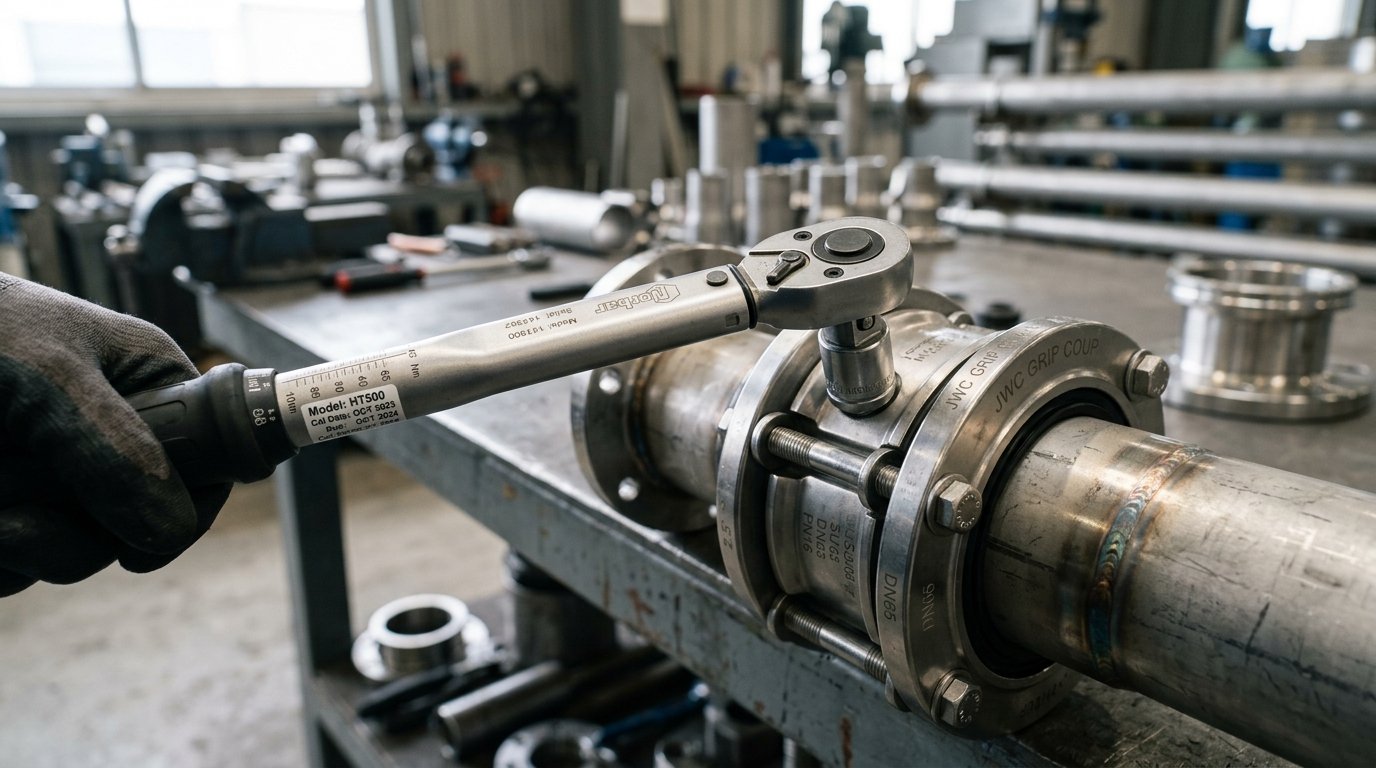
Use a calibrated torque wrench. A standard hand wrench produces highly variable torque — the same installer applying “firm” force to the same bolt will vary by 30–50% run to run, depending on posture, grip, and arm angle. A calibrated torque wrench removes this variation. It should be calibrated to a traceable standard and within its calibration interval — a torque wrench that has not been serviced in years may read accurately but deliver a different actual torque due to internal spring fatigue or wear.
Re-check after initial pressurisation. New gaskets continue to seat and compress slightly during the first pressurisation cycle. The housing comes to its final geometry as the fluid pressure loads the joint for the first time. A re-torque pass within 24–48 hours of first commissioning — without loosening the bolts first, simply applying the torque wrench at the specified value — confirms that no bolt has relaxed below specification and that the gasket has stabilised. On high-vibration applications (pump discharge, compressor lines), a scheduled re-check at a defined service interval is best practice.
Document the installation. For marine class and industrial pressure-system records, note the coupling model, nominal diameter, bolt torque specified, calibrated wrench serial number, and date of installation. This record supports any future inspection, leak investigation, or system modification without requiring the joint to be disassembled for identification.
Key Takeaways
- Pipe coupling bolt torque specs are coupling-specific. The correct value depends on bolt size, coupling model, pipe diameter, and gasket material. The manufacturer’s datasheet is the only authority — never carry over a value from a different model or size.
- Under-torquing and over-torquing both cause joint failure. Under-torquing leaves the gasket incompletely compressed; over-torquing extrudes or distorts it. Both produce leaks. Use a calibrated torque wrench for the final pass — not a hand wrench, and not an impact driver.
- The staged cross-pattern method is non-negotiable. Three passes at 30% / 60% / 100% of final spec, in an alternating cross sequence, ensures the gasket compresses uniformly around the full circumference of the joint.
- For JWC grip-type couplings, torque activates the grip ring. Correct torque is not only about the gasket seal — it determines whether the grip ring (MJG, MJGL, MJGF, MJGFL) fully engages to resist axial pull-out. Under-torquing compromises both the seal and the mechanical restraint.
- Gap setting and angular deflection limits must be respected. JWC MJG-family gap tolerances (0–8 mm for 15A–65A; 0–15 mm for 80A+) and deflection limits (5° / 4° / 2° by size) are the geometric conditions under which the specified bolt torque produces the rated joint performance.
About David Phee Enterprise
David Phee Enterprise is the exclusive Singapore distributor for Jeong Woo Coupling (JWC) and a long-standing supplier of Aju, Romacon, and Smith-Blair pipe couplings, repair clamps, and expansion joints. Operating from Empire Technocentre in Kaki Bukit, DPE supplies ship chandlers, shipyards, and industrial contractors across Singapore, Malaysia, and Indonesia — providing JWC installation documentation including torque specifications and gasket compatibility guidance alongside same-day delivery on stocked sizes. Visit davidphee.com for datasheets, torque tables, and technical support.