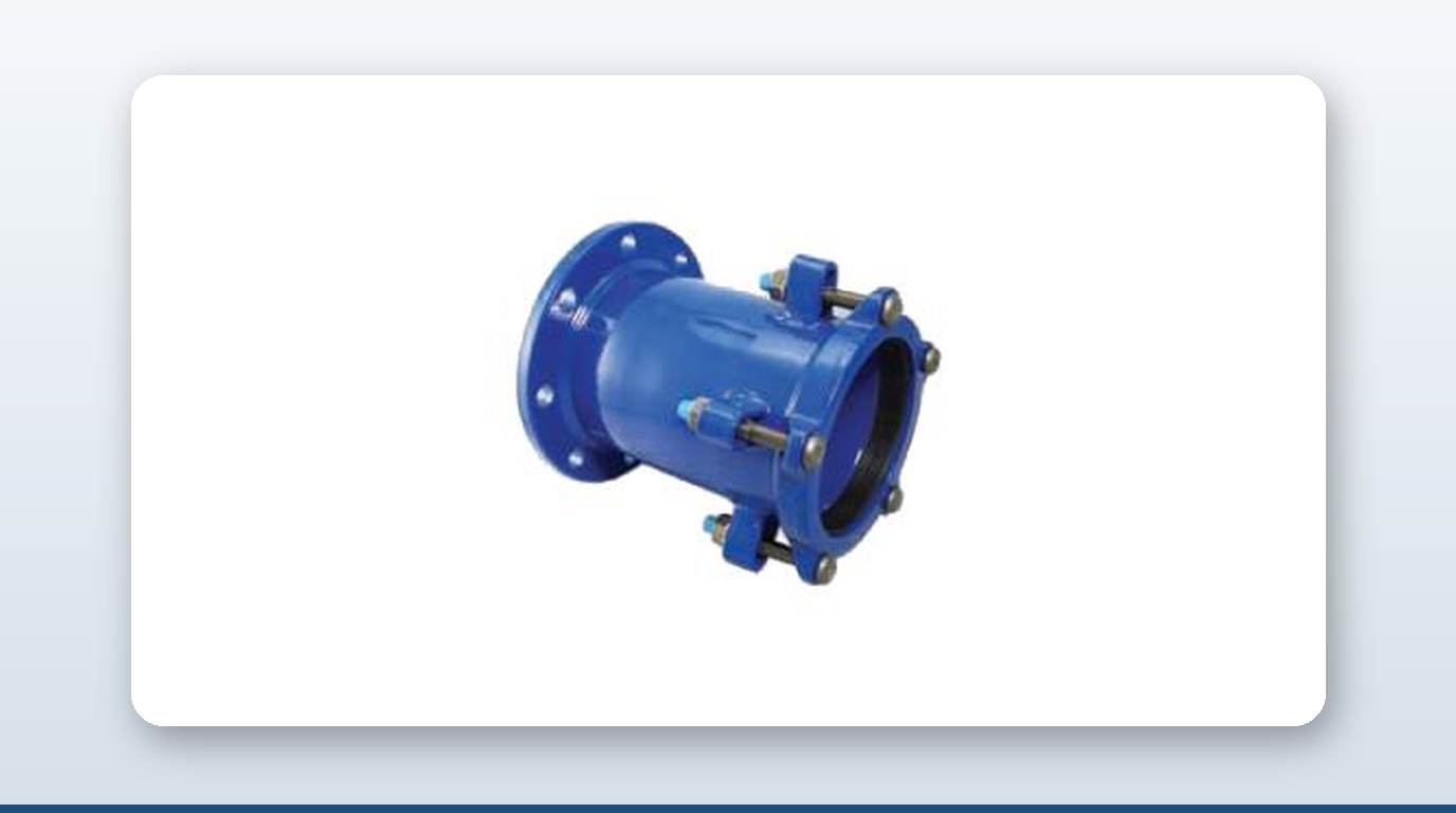
Stainless steel survives in seawater for one reason only: a passive chromium-oxide film barely two to three nanometres thick that re-forms within milliseconds if scratched. Pitting corrosion happens when chloride ions punch through that film faster than it can heal. Crevice pitting corrosion marine pipe failure is the same mechanism with the geometry pre-built — a gasket clamped against a flange face creates a tight, oxygen-starved gap that attacks the same alloy at a temperature 20–40°C lower than open-surface pitting would. For anyone specifying flanged or bolted coupling joints on a seawater line, that gap is where the failure usually starts.
This article covers the mechanism behind both pitting and crevice attack, the PREN ranking system and the ASTM G48 test methods used to grade alloys against it, why the gasket itself is half the failure mode, which gasket materials make a crevice worse or better, five documented failure cases, and the working prevention rules drawn from them.
Pitting vs Crevice Corrosion — Same Mechanism, Different Geometry
Pitting corrosion starts when chloride ions breach the passive film at a microscopic defect and the bare metal underneath can’t re-passivate fast enough. The pit then grows autocatalytically: metal cations migrate out, chloride ions migrate in, the pit interior turns acidic and oxygen-depleted, and it tunnels inward through the wall thickness.
Crevice corrosion is the identical mechanism but with the geometry already built in. A gasket pressed against a flange face creates a tight gap — typically 25–100 µm — right at the metal surface. Oxygen inside that gap is consumed within hours and can’t be replenished by diffusion through the gasket. The crevice interior becomes anodic relative to the freely-exposed surface outside it, the interior pH drops below 1 from hydrolysis of dissolved metal cations, and chloride concentration inside the crevice can reach 10 times the bulk seawater level. The result: crevice corrosion initiates at temperatures 20–40°C lower than pitting on the same alloy, and the attack concentrates right at the gasket OD or ID — exactly the worst place to lose wall thickness.
Measuring Resistance — ASTM G48, CPT, CCT, and PREN
The crevice-corrosion-resistance test of record is ASTM G48 Methods B/D/F — multiple-crevice assemblies bolted onto a flat specimen, immersed in 6% ferric chloride (Methods B/D) or ferric chloride plus hydrochloric acid (Method F), held at progressively higher temperatures until visible attack initiates. The temperature where attack first appears is the Critical Crevice corrosion Temperature (CCT). Methods A/C/E give the pitting analogue, the Critical Pitting Temperature (CPT). ASTM G150 is an electrochemical alternative run in 1 M sodium chloride at a fixed potential.
PREN — the Pitting Resistance Equivalent Number — is the composition-based ranking formula: PREN = %Cr + 3.3 × %Mo + 16 × %N. The widely cited threshold for reliable ambient-seawater crevice resistance is PREN ≥ 40.
One important caveat: the CPT/CCT numbers from 6% FeCl₃ testing are deliberately aggressive — they’re a relative ranking tool, not a max-service-temperature spec. Real seawater is less aggressive than ferric chloride, so an alloy’s actual service limit in seawater is typically higher than its G48 CPT, sometimes by 20–40°C. Use the table below to compare alloys against each other, not to set an absolute temperature rating.
CPT / CCT / PREN by Alloy
All CCT values below are from 6% FeCl₃ G48 testing unless noted.
| Alloy (UNS) | Typical PREN | CPT (°C) | CCT (°C) | Seawater verdict |
|---|---|---|---|---|
| 304L (S30403) | ~19 | < 0 | < −5 | No — pits at room temperature in seawater; fresh-water only |
| 316L (S31603) | ~25 | ~15 | ~−5 to 0 | Marginal — crevices below ambient under any gasket; not for permanent submerged or static-water service |
| 904L (N08904) | ~34 | ~35–40 | ~10–20 | Borderline — better than 316L but still crevices under tight gaskets in ambient seawater |
| Duplex 2205 (S32205) | ~35 | ~30–35 | ~15–25 | Borderline — fails the PREN ≥ 40 rule for ambient seawater crevice resistance |
| 6Mo super-austenitic — 254 SMO (S31254) | ~42–44 | ~85–90 | ~35–45 | Yes — passes PREN > 40; can sit in natural seawater at 60°C for prolonged periods without crevice attack |
| 6Mo super-austenitic — AL-6XN (N08367) | ~45–47 | ~74 base metal; ~39 autogenous TIG weld | ~35–45 | Yes — equivalent crevice rating to 254 SMO; welds need overmatched filler |
| Super duplex 2507 (S32750) | ~41–43 | ~78–90 | ~35–50 | Yes — the preferred answer for high-strength seawater couplings |
| Hastelloy C-276 (N10276) | ~65–70 | >150 | ~60 | Yes, premium — practically immune in ambient seawater |
| Titanium Grade 2 / 7 | n/a | Effectively immune | Effectively immune | Yes, premium — standard service for SWRO and heat-exchanger tubes |
At every PREN tier below 40, the CCT is below ambient seawater temperature — meaning crevice corrosion can initiate the moment the gasket is bolted up in tropical waters.
Why the Crevice Forms at the Gasket Edge
A gasket forms two annular contact bands on a flange face — the outer edge against the flange face, the inner edge against the bore. Bolt-up pressure squeezes the gasket, but at the very edges that contact isn’t hermetic — there’s always a 10–100 µm capillary gap. Seawater wicks into it, the oxygen inside is consumed within hours and can’t diffuse back through the gasket, and the gap becomes anodic relative to the freely-aerated flange face outside the bolt circle. Current density at the gasket edge can run up to 1,000 times the freely-corroding rate elsewhere on the flange.
Three things make it worse. Tight, non-absorbing gaskets — PTFE solid sheet or PTFE-envelope — don’t absorb water, so the gap stays full of stagnant seawater. Graphite-loaded gaskets are electropositive to stainless, setting up a galvanic cell on top of the crevice cell — the worst-case combination. And flange-face surface finish matters: faces rougher than Ra 6.3 µm leave channels that let seawater preferentially into the crevice, while faces smoother than Ra 1.6 µm reduce gasket bite and let it creep. The target band is Ra 3.2–6.3 µm for soft-faced or spiral-wound gaskets, and Ra 1.6–3.2 µm for ring-type-joint gaskets.
Gasket Material and Crevice Severity
| Gasket type | Crevice severity on stainless in seawater | Notes |
|---|---|---|
| PTFE solid sheet / PTFE envelope | High — tight, non-absorbing | Triggered documented North Sea 6Mo flange failures; avoid as default on stainless seawater joints |
| Graphite-loaded (spiral wound, sheet) | Very high — galvanic and crevice combined | Banned by most marine specs on stainless |
| Synthetic aramid fibre (Klingersil-type) | Low to moderate | The proven retrofit fix on failed 6Mo flange installations |
| Natural rubber / EPDM / NBR elastomer sleeve | Low | Absorbs a small amount of water, keeping the crevice less stagnant, and conforms to fill micro-asperities |
| Kammprofile (serrated metal core + soft facing) | Moderate, facing-dependent | Graphite facing is bad on stainless; use non-graphite facing only |
| Spiral-wound, alloy-matched filler | Low if filler matches flange alloy | Premium retrofit for seawater flange interfaces |
Documented Failures
A high-pressure pump on a Red Sea SWRO plant tripped on high vibration after 750 hours; the super-duplex S32760 shaft had fractured from crevice corrosion initiating at the impeller/shaft-sleeve interface, even though the alloy itself was correctly specified. A cast super-duplex seawater pump in a Mediterranean SWRO plant was found with crevice corrosion at the gasket location and severe pitting on open surfaces — investigators concluded the gasket-induced crevice geometry overrode the alloy’s nominal PREN rating. Filtersafe, a ballast-water-treatment filter manufacturer, upgraded screens from 316L (PREN ~25) to 904L (PREN ~34) after repeated failures and reported an 82% improvement in service life — even though 904L still doesn’t pass the PREN ≥ 40 rule. A side-by-side Gulf of Mexico offshore tubing trial showed austenitic 316 tubing with heavy crevice and pitting corrosion within months, while 2507 super-duplex tubing in the same bundle showed no corrosion. And a series of North Sea 6Mo stainless flange failures traced not to the alloy but to PTFE gaskets creating tight, oxygen-depleted crevices — the proven fix was re-machining the flange faces and switching to synthetic-fibre gaskets, with no further failures on the same alloy.
Prevention Rules
1. Specify PREN ≥ 40 (6Mo super-austenitic, super duplex 2507, or higher) for any permanent submerged or static seawater service; anything below needs cathodic protection, a less-aggressive gasket geometry, or fresh-water-only service. 2. Gasket geometry beats alloy choice in many real failures — avoid PTFE-solid and graphite-loaded gaskets on stainless seawater joints; default to synthetic fibre or elastomer. 3. Specify flange-face surface finish on the drawing: Ra 3.2–6.3 µm for soft-faced/spiral-wound gaskets, Ra 1.6–3.2 µm for ring-type joints. 4. Eliminate the crevice where possible — welded joints beat bolted joints in seawater; where bolting is required, use raised-face flanges and full bolt torque so the gasket actually conforms. 5. For alloys below PREN 40, layer defences: cathodic protection (sacrificial anode at the housing), a non-graphite synthetic-fibre gasket, and a sealant fillet around the gasket OD to keep liquid water out of the crevice band. 6. Watch temperature — even on 6Mo or super duplex, the practical chlorinated-seawater limit in creviced flanges is around 40°C; above that, step up to a nickel-base alloy or titanium. 7. Treat welds as a CPT/CCT penalty zone — AL-6XN base-metal CPT is around 74°C but drops to around 39°C at an autogenous TIG weld, so overmatched nickel-rich filler is needed to hold the weld’s crevice resistance close to the base metal.
Key Takeaways
- – PREN ≥ 40 is the ambient-seawater crevice-resistance threshold; common marine-grade alloys 316L (~25), 904L (~34), and duplex 2205 (~35) all fall below it.
- – Crevice corrosion initiates 20–40°C lower than open-surface pitting on the same alloy, because the gasket gap depletes oxygen and concentrates chloride to roughly 10 times the bulk seawater level.
- – PTFE and graphite-loaded gaskets create the most severe crevices on stainless flanges; synthetic fibre or elastomer gaskets are the proven safer default.
- – Filtersafe’s upgrade from 316L to 904L ballast-water-treatment screens delivered an 82% improvement in service life, even though 904L still falls short of the PREN ≥ 40 rule.
- – Flange-face finish has a narrow target band — Ra 3.2–6.3 µm for soft-faced/spiral-wound gaskets, Ra 1.6–3.2 µm for ring-type joints — outside of which the joint either leaks or channels seawater into the crevice.
- – Even alloys above PREN 40 aren’t automatically safe: a correctly-specified super-duplex pump shaft still failed from crevice corrosion at a tight metal-to-metal shaft-sleeve interface.
About David Phee Enterprise
David Phee Enterprise is the exclusive Singapore distributor for JWC pipe couplings, stocked at Empire Technocentre, Kaki Bukit for same-day delivery, alongside Romacon repair clamps and Helden wide-tolerance fittings for the flanged, gasketed joints where crevice attack concentrates. DPE’s standard EPDM/NBR elastomer sleeve gasketing is already the safer gasket geometry — but the wetted housing alloy on most stock marine couplings still sits below the PREN 40 threshold, so for permanent seawater or BWTS service, ask about duplex or 6Mo upgrade options before specifying. For coupling specs or certification documentation on any of these ranges, contact DPE or browse the full catalogue at davidphee.com. Related reading: stainless vs carbon steel pipe couplings and NBR/EPDM/Viton gaskets for pipe couplings.