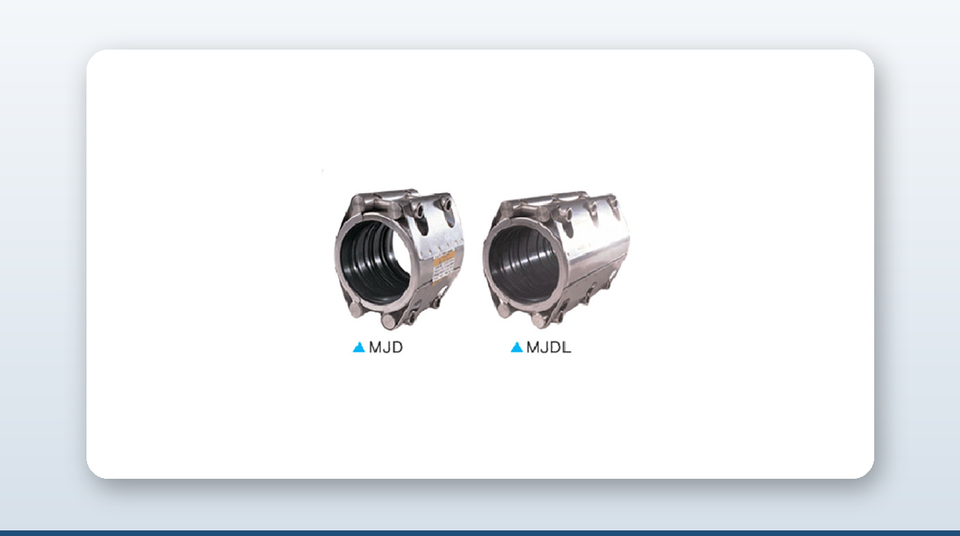
Seawater systems are sized for a bulk pipe velocity of around 3 m/s, but that number rarely matters at the point of failure — because the coupling, not the pipe, is almost always where erosion corrosion seawater piping damage starts. At every slip-on coupling, repair clamp, or expansion joint, a gasket step, a misaligned pipe end, or an annular cavity locally re-accelerates the flow and concentrates wall shear stress far above the bulk-pipe value. That’s where the protective oxide film gets stripped first, and it’s where 90/10 cupronickel, 316L, and 22Cr duplex all start losing wall thickness.
This article covers the erosion-corrosion mechanism and the wall-shear thresholds behind it, the specific flow-disturbance geometries that form at coupling joints, per-alloy velocity ceilings for continuous seawater service, what happens to those ceilings in dirty or polluted harbour water, and the field-installable design rules that keep a coupling out of the failure register.
The Mechanism — Turbulence Stripping the Protective Film
Erosion-corrosion — also called flow-induced localized corrosion (FILC), and historically impingement attack at flow-disturbance geometry — is a two-step, synergistic process specific to passive-film alloys in seawater. First, the alloy survives in seawater because of a thin protective film: a Cu₂O/Ni-Cu₂O layer on cupronickel, a chromium-rich oxide on stainless steels. Second, when local wall shear stress exceeds a critical threshold, that film is mechanically stripped off faster than it can re-form. The freshly exposed bare metal corrodes rapidly, the film re-forms, gets stripped again, and the pit deepens. This is not classic abrasive erosion, although suspended sand makes it dramatically worse — it’s a fluid-mechanical attack on the passive film itself.
The critical wall shear stress for 90/10 cupronickel in artificial seawater is higher than the 43 Pa figure once cited industry-wide: with a properly pre-formed film, 90/10 tolerates up to 370 Pa; with as-delivered surface and light hypochlorite chlorination, the threshold drops to around 200 Pa before erosion-corrosion initiates. That gap between 43, 200, and 370 Pa is why the industry now talks about commissioning protocols — running unchlorinated seawater through a new system for a period to let the protective scale mature — rather than relying on velocity limits alone.
Where It Concentrates — Flow Disturbance at the Coupling
The bulk-pipe velocity is almost never what kills the coupling; what matters is the local velocity and shear at the step change. Three geometric flaws repeatedly show up in failure analyses.
Gasket protrusion or over-squeeze. When a coupling gasket is sized incorrectly or over-tightened, the rubber ID bulges into the bore, the flow contracts past it (a vena contracta), accelerates, then re-expands into the downstream pipe, generating a separated recirculating zone. Erosion rates downstream of a protrusion can run an order of magnitude higher than in the unobstructed pipe.
Step change or misalignment at the joint. Slip-on couplings join two pipe ends that may differ in OD, ID, wall thickness, or roundness. Any radial step — even 1–2 mm — acts as a backward-facing step on the inlet side and a forward-facing step on the outlet side, and a backward-facing step creates a reattachment zone roughly 5–7 times the step height downstream, where shear stress peaks. This is the reason industry guidance keeps elbows and other disturbances at least 5 pipe diameters downstream of a coupling: two disturbances stacked back-to-back multiply, they don’t just add.
Annular cavity at the gasket recess. Some coupling designs leave a small annular gap between the two pipe ends, sealed by the gasket. In seawater this cavity simultaneously traps stagnant water that goes anaerobic and seeds microbially influenced corrosion, and generates a recirculating eddy at the pipe-gasket interface that grooves the pipe ID circumferentially — the classic “wedding ring” failure pattern seen at couplings.
Repair clamps add a fourth pattern: they cover an existing hole or wall-thin spot, and the flow under the clamp sits inside an enlarged cavity. Local velocity drops — good for the substrate — but turbulence and shear at the cavity edges increase, and repair clamps on seawater lines tend to migrate the resulting failure 1–2 pipe diameters downstream of the clamp itself.
Velocity Limits by Alloy
All values below are for continuous service in clean-to-moderately-fouled marine seawater at ambient temperature (roughly 25–30°C). Cut these by 30–50% for dirty seawater (entrained sand, sulphide-bearing, biofouled); intermittent service tolerates roughly double these limits.
| Alloy | Pipe-run max design velocity (m/s) | Heat-exchanger tube max (m/s) |
|---|---|---|
| 90/10 CuNi (C70600) | 3.5 | 2.5 |
| 70/30 CuNi (C71500) | 4.0–4.5 | 3.0 |
| 316L stainless | 2.0 (dirty SW), 3.0 (clean) | Avoid in raw SW |
| 904L (N08904) | 3.0–4.0 | 3.0 |
| 22Cr duplex 2205 (S32205) | 6.0 | 4–5 |
| 25Cr super-duplex 2507 (S32750) | 7.0 | 5–6 |
| 6Mo austenitic (AL-6XN / 254SMO) | 7.0 | 5–6 |
| Titanium Grade 2 (R50400) | >30 (effectively unlimited) | >30 |
For 316L, the British Stainless Steel Association’s own position is blunt: “316 cannot be considered corrosion-proof in seawater” — it pits and crevice-corrodes under deposits even at low velocity. Titanium’s limit isn’t metallurgical at all; erosion-corrosion stays negligible even at 36–40 m/s with sand entrainment, so the real constraint is hydraulic pressure-drop and reaction force, not the metal.
The API RP 14E C-Factor — Why the Old Rule Undersizes CRA Piping
The classic API RP 14E erosional-velocity C-factor (C = 100 continuous / 125 intermittent) works out to roughly 3 m/s in seawater, and is now widely regarded as over-conservative for corrosion-resistant-alloy (CRA) piping in clean water. Recent industry consensus allows C = 450 for CRA seawater-injection service — up to roughly 15 m/s — provided there’s no sand. Don’t quote API 14E as a hard limit for cupronickel or duplex couplings; use the alloy-specific velocity table above instead.
What “Dirty Seawater” Does to the Ceiling
Three independent insults pull the velocity ceiling down sharply. Entrained sand or silt — coastal intakes and sea-chests routinely carry 50–500 mg/L suspended solids — strips the protective film locally on every particle impact; for CuNi, the 3.5 m/s limit drops to around 2.5 m/s, and for 316L, 2 m/s drops to around 1 m/s. Biofouling — mussels, barnacles, and slime layers creating downstream wakes that act like permanent flow disturbers — is the primary reason raw-seawater 316L is limited to 2 m/s rather than 3 m/s. And sulphide attack in polluted-harbour water — the Singapore Strait is cited alongside the Houston Ship Channel and oil-loading terminals as carrying 0.01–0.1 ppm dissolved H₂S — poisons cupronickel film formation, collapsing its velocity limit to under 2 m/s and accelerating crevice corrosion in stainless. ISO 21457 specifically flags polluted-harbour service as out-of-scope for 6Mo alloys unless cathodically protected.
Field-Installable Design Rules
1. Gasket ID must equal pipe ID, cut flush with no inward protrusion. 2. Pipe ends should be square-cut, deburred, and chamfered — any burr or angled cut at a slip-on coupling becomes a local trip wire for turbulence. 3. Reducer taper angle should stay under 19° (total included angle under 40°) — steeper reducers shed turbulence into the downstream coupling. 4. Keep at least 5 pipe diameters between disturbances — no coupling immediately downstream of a pump, valve, elbow, or T-junction. 5. Use a bend radius of at least 1.5 times the pipe diameter for long-radius elbows in CuNi and stainless seawater lines. 6. Subtract 0.25–0.5 m/s from the velocity limit when rolled-over flanges, raised gaskets, or oversized weldolets are present. 7. Pre-condition the film — new CuNi systems should run unchlorinated, ambient seawater for six weeks before chlorination begins, which roughly doubles the critical shear-stress tolerance. 8. Avoid stagnation — maintain a minimum velocity of 1 m/s in any seawater line carrying suspended matter; below 1 m/s sediment drops out, and below 0.5 m/s biofilm anchors.
Documented Failure Patterns
Condenser-tube inlets are the classic case: 70/30 and 90/10 CuNi heat-exchanger tubes consistently fail in the first 300 mm of the inlet end, where the tube-sheet step combines with flow-entry turbulence and impingement — reported in failure-analysis literature as “horseshoe pitting,” and the reason heat-exchanger velocity limits sit lower than pipe-run limits. Naval seawater pump casings have failed in as little as 18 months after operators uprated impeller speed, pushing local discharge velocity past the critical shear threshold — the pump discharge spool, typically a slip-on coupling or short flanged stub, perforated first. A documented slip-on coupling installed at a tee — two disturbances back-to-back within 2 pipe diameters — saw the gasket annulus eddy and the downstream pipe wall groove circumferentially within 12 months, the same pattern seen with repair clamps installed over already-corroded pipe. And intermittent high-velocity service — ballast and cargo-wash lines on tankers running at 6 m/s or more for 30 minutes, then sitting static for days — is a worst case for CuNi, since the film never matures between cycles; OCIMF’s SIRE 2.0 question library flags seawater-line wall-thickness surveys as a critical tanker inspection item as a result.
Key Takeaways
- – The coupling, not the pipe, is almost always where erosion-corrosion starts, because gasket protrusions, step changes, and annular cavities locally re-accelerate flow and raise wall shear far above the bulk-pipe value.
- – The critical wall shear stress for 90/10 CuNi ranges from around 200 Pa (as-delivered, chlorinated) to around 370 Pa (mature, unchlorinated film) — both well above the older 43 Pa figure once used industry-wide.
- – Continuous-service velocity ceilings: 90/10 CuNi 3.5 m/s, 70/30 CuNi 4.0–4.5 m/s, 316L 2–3 m/s, super duplex 2507 and 6Mo 7 m/s, titanium effectively unlimited above 30 m/s.
- – A six-week unchlorinated commissioning run lets new CuNi systems grow a mature protective film before chlorination begins, roughly doubling their shear-stress tolerance.
- – Polluted-harbour water — the Singapore Strait is cited as an example — carries enough dissolved sulphide to poison cupronickel film formation, collapsing its velocity limit to under 2 m/s.
- – Field design rules call for gaskets cut flush with the pipe ID, square-cut chamfered pipe ends, and couplings kept at least 5 pipe diameters from any pump, valve, or elbow.
About David Phee Enterprise
David Phee Enterprise is the exclusive Singapore distributor for JWC pipe couplings, stocked at Empire Technocentre, Kaki Bukit for same-day delivery, alongside Romacon repair clamps and Helden wide-tolerance fittings for the sea-water cooling and ballast lines where flow-induced erosion concentrates at the coupling gasket rather than the pipe wall. For coupling specs or certification documentation on any of these ranges, contact DPE or browse the full catalogue at davidphee.com. Related reading: ballast water treatment piping and BWTS couplings and pipe coupling corrosion material selection.